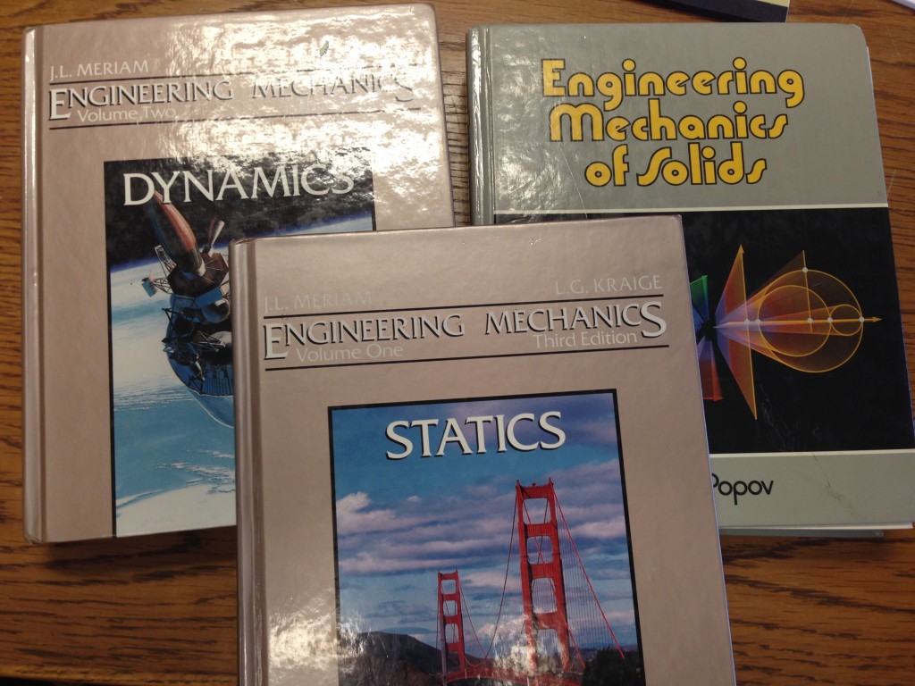
The first time I had to deal with a statics problem was first semester physics. It wasn’t too crazy – something like levers to introduce the concept of balance of forces and moments. Later, we would enjoy an entire semester-long course dedicated to statics. Beam analysis, trusses, multiple point loads, concentrated moments and other tricks Professor Meyer threw at us during his infamous Friday morning pop quizzes. It was a 7 am class, so quizzes were on Friday to make sure we showed up.
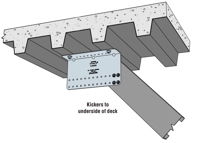
A few weeks back, we were developing anchor reactions for the new SJC steel-joist connectors when used in a kicker application. We wanted to publish anchor reactions for the given connector allowable loads so engineers could skip that step in the calculations.
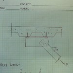
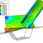
First step was a lot like statics class. Draw a free body diagram with loads and resolve the reactions. A simple model ignoring eccentricity gave us a load we knew was too small. Adding eccentricity and prying forces gave us a load that seemed way (way!!) too large. We used finite element models to better understand the forces in the connection.
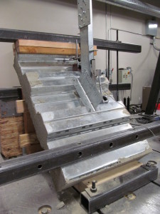
Of course, there is no substitute for physical testing. So we also designed a test setup to capture the anchor tension forces directly. Eliminating as much friction from the setup as possible required some precision machining, several rounds of trial and error and a lot of patience from the lab technicians building everything. The mechanics of the final setup are fairly straightforward. The anchor rods attach to the blue load cells, which measure the tension forces in the rod directly.
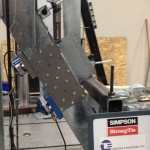
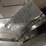
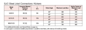
The test results correlated very well with the original FEA models. I still marvel at the number of tests that go into creating one number for a load table. Of course, even knowing the anchor forces, we still ran a series of tests in metal deck – just to be sure.
Let us know what you think about the testing in the comments below.


I’m not surprised that the testing corresponded closely to the computer simulation. I know you’ve spent a lot of time calibrating the model, so I would expect the results to align. My question is how closely did the final results correspond to the initial simple statics calculations? Did you find that your two simple statics calculations properly enveloped the real solution? Was one a better predictor than the other model?
Sadly, the calculation is not that impressive. The direct load (ignoring eccentricity) is some trigonometry. My oldest son is doing trigonometry in school and he doesn’t believe we actually use this stuff. I’ll have to show him this blog post. If we try to account for eccentricity and prying action, we get a higher force, as you’d expect since we are basically amplifying the direct load by the ratio of the length of the part and the eccentricity.
From experience, we know that calculating connectors as if they were perfectly rigid bodies yields conservative results. Thin parts (say 10 gage and thinner) yield and forces redistribute, so the prying action is lower. So testing is preferred to understand the true performance. In the summary table, I’ve listed the tested anchor forces (what’s published) and the values from calculating the forces by the two methods. Ignoring eccentricity underestimates the force by a lot, as you would expect. Including eccentricity in the calculation is conservative and not too bad. But it does overestimate the anchor tension by up to 70%. ACI 318 Appendix D anchorage design is tough enough as it is, so we want to be as accurate as we can.
Peter’s question is exactly why I logged on to discuss! Additionally, would you mind sharing each of the calculations with their results along with the results from testing? It would be a fantastic thing for engineers like myself to see, who don’t get the luxury of dealing with test results regularly. Thanks!