This week, I’d like to introduce Jeff Ellis as a guest blogger for the Structural Engineering Blog. Jeff is the Manager of Codes, Standards and Special Projects for Simpson Strong-Tie. Jeff will be posting occasionally on topics that are relevant to our work, especially related to cold-formed steel (CFS) construction.
When was the last time you knew an earthquake was coming and witnessed its effects on a building without feeling any shaking yourself? Since the mid- to late ‘90’s, several uni-axial and tri-axial shake tables have been built and used to better understand whole building performance under actual earthquake ground motion in order to improve code requirements and, in some cases, develop performance-based design methods.
Performance-based design methods enable the owner to choose, and the engineer to design, for a specific type of desired building performance, such as collapse prevention or immediate occupancy following the maximum considered earthquake, rather than just following prescriptive code requirements.
For light-frame construction, Simpson Strong-Tie conducted shake table testing of our Wood Strong-Wall® Shearwall at the University of British Columbia in the late 90’s, CUREE ran shake table tests at UC San Diego and University of British Columbia in the early 2000’s, and the NEESWood project ran shake table tests at University at Buffalo in 2006 and E-Defense in Japan in 2009.
Shake table testing generally uses one or two earthquake records while the FEMA P-695 seismic force-resisting system design coefficient and factor analysis procedure requires several archetypical buildings for a given material or system type to be evaluated using 22 pre-defined earthquake ground motions. Therefore, after developing computer models that best match component and shake table testing, further analysis using additional earthquake records is performed to determine the adequacy of a seismic force-resisting system design procedure and its response modification coefficient and factors.
A few weeks ago, I attended the AISI Committee on Specification (COS) and Committee on Framing Standards (COFS) meetings held in Buffalo, New York. Committee members could watch the CFS-NEES full scale tri-axial shake table testing of a two-story cold-formed steel framed office building at the University at Buffalo Structural Engineering and Earthquake Simulation Laboratory. The University at Buffalo CFS-NEES portion of the project began in April and will go through August.
The purpose of CFS-NEES is to improve the understanding of overall system performance of CFS framed buildings in order to develop performance-based design methodology for the seismic force-resisting elements of these buildings, as well as continuing to improve the design and detailing requirements for CFS-framed seismic force-resisting systems.
The project team includes professors and students from Johns Hopkins University with principal investigator Professor Ben Schafer, Bucknell University, McGill University, and the University of North Texas as well as an engineer from Devco Engineering. The project includes a 12-person Industry Advisory Board made up of AISI representatives, design engineers, and manufacturers.
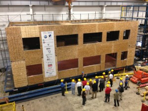
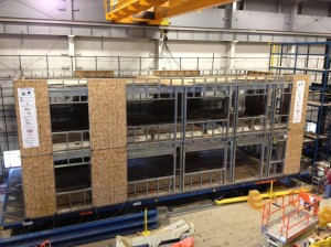
The two-story building, shown in Figure 1, is 23 feet wide by 50 feet long with a first and second story height of nine feet. It’s framed with six inch wide by 54 mil (16 ga) studs (600S162-54) at the first story and 43 mil (18 ga) studs at the second story, spaced at 16 inches on center and having bridging at midheight. The roof joists are 1200S200-54 and the floor joists are 1200S250-97 at 24 inches on center and are framed into a ledger attached to the side of the wall studs, shown in Figure 2.
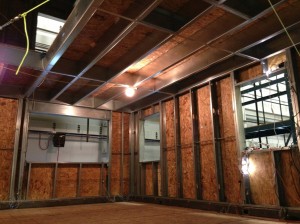
The floor and roof diaphragms and the two-story stacked CFS framed shear walls, unsymmetrically placed and located only at the building perimeter, are sheathed on their exterior with OSB structural wood sheathing, shown in Figure 3. The other non-shear walls are also sheathed on their exterior with OSB structural wood sheathing to fur them out for the application of DensGlass® fiberglass mat gypsum exterior sheathing. The interior walls and ceilings have gypsum board finishes.
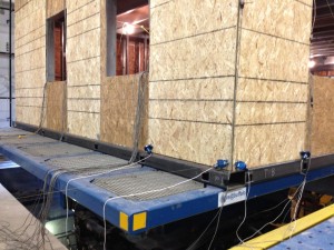
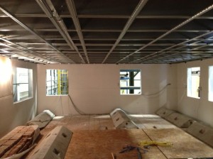
Additional weight was added to the second floor and roof, shown in Figure 4, to ensure the building had a similar mass (approximately 77,500 pounds) depending on the structural sheathing and finish materials added during the various testing phases. Additional mass and framing was added to the roof to simulate a mechanical unit and framing to support it and the second floor contains two openings: a back stairway (14.5 ft. x 3 ft.) and an opening to the first floor (8 ft. x 10 ft.) that will also include a stairway. For design purposes, the project location is in Orange County in southern California at 33.8 degrees latitude and 117.86 degrees longitude.
The various shake table test phases include shake table testing:
(1) with only the CFS framed roof and floor diaphragms and shear walls sheathed, as shown in Figure 5, destructively tested and removed,
(2a) building rebuilt same as in Phase 1,
(2b) same as 2a and with exterior non-shear walls sheathed added,
(2c) same as 2b and with the interior of the exterior walls sheathed with gypsum board added as shown in Figure 6,
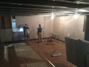
(2d) same as 2c with foundation floor system for which to build interior walls upon, gypsum board installed on interior walls and ceilings and timber stairs added, and
(2e) same as 2d with the exterior walls sheathed with DensGlass® over the wood structural sheathing added.
The primary earthquake records for this testing are 100% of the 1994 Northridge Earthquake Canoga Park record (1.0g 0.2 second Spectral Response Acceleration) to simulate the Design Basis Earthquake (DBE) and 100% of the Northridge Earthquake Rinaldi record (1.5g 0.2 second Spectral Response Acceleration) to simulate the Maximum Considered Earthquake (MCE).
The purpose of the nondestructive shake table tests is to investigate the difference in building behavior with different materials and components added before it’s damaged. Phase 1 tested the building to 100% of the Canoga Park record and the building was removed and re-built for the next phases. Most of Phase 2 tests were to 44% of the Canoga Park record, as this was the strongest nondestructive testing for this record and building, but Phase 2e will be tested to 44% and 100% of Canoga Park followed by 100% of the Rinaldi earthquake record.Our group witnessed the Phase 2b testing to 44% of the Canoga Park earthquake record.
To investigate damage, the building is shaken with what’s called two sets of “white noise” tests in each of the three directions (two horizontal and vertical) prior to the primary test and then shaken again after the primary test to determine what, if any, differences occurred, such as the building period. These white noise tests are random excitations with average peak ground accelerations of 0.05g and 0.1g and are intended to excite a wide range of frequencies to characterize the complete frequency response of the structure.
For Phase 1, the building period was 0.32 seconds before the test and 0.56 seconds after and the damping was approximately 4% before and 18% after. In Phase 2, the addition of OSB furring sheathing decreased the building period from 0.32 to 0.2 seconds and building damping increased by approximately 3% in the long direction (period and damping values similar in the short direction) and the maximum story drift in Phase 1 and 2a tests was 1.9 inches from floor to floor.
In Phase 2d with the gypsum board finishes on the interior of the exterior walls and ceilings, the period decreased to 0.17 seconds and the damping increased by about 3%. Load cells were added to the shear wall hold-downs. Some hold-downs in some of the shear walls were in tension at the same time versus our typical simplified component level assumptions of a compression-tension couple.
Also visit the CFS-NEES Blog by Kara Peterman, Johns Hopkins University graduate student for more information on the project.
What are your thoughts? Visit the blog and leave a comment!


Great article and summary Jeff! Note the final 100% test is planned for Friday, August 16, and can viewed live online. See the CFS-NEES Blog site mentioned in the article for the link. All research reports thus far, including the engineering design calculations and drawings for the building, are posted on the CFS NEES website.
The video of the CFS-NEES full scale, 100% Northridge Rinaldi record shake table test for the finished building that was run today may be seen on YouTube at http://www.youtube.com/watch?v=RXBi66k-Xo0.