

“Change is the only constant in life” and “When you are finished changing, you are finished” are quotes from the ancient Greek philosopher Heraclitus and Benjamin Franklin, respectively. I’m reminded of them as I review the numerous changes to codes and standards during the typical three to five-year development cycles. While code and standard changes can be challenging to incorporate into our work, they typically offer an improvement or expansion of design and construction solutions.
Author: Jeff Ellis
Jeff is a licensed Civil and Structural Engineer in California and multiple other states who has been practicing since 1991. Before joining Simpson Strong-Tie in 2000, he spent nine years as a design engineer on residential, commercial, institutional, and forensic projects, working in wood, cold-formed steel, structural steel, masonry, and concrete. At Simpson Strong-Tie, he has held roles spanning branch engineering, regional engineering management, codes and product compliance, and business unit leadership. He currently serves as Manager for Engineering Department Operations. His industry involvement includes serving as chairman of the AISI Committee on Framing Standards Lateral Design Subcommittee, president of both SEAOSC and the Cold-Formed Steel Engineers Institute (CFSEI), and as a member of the ICC-ES Board of Managers. He is a SEAOC Fellow and current co-chair of the SEAOSC Legislative Action Committee, and has authored design guides and technical articles and presented on structural design and codes and standards topics throughout his career.

Questions Answered: Yield-Link® Moment Connection for Steel Construction
In this post, we follow up on our May 2 webinar, Seismic Resilience and Risk Assessment of the Yield-Link® Connection for Steel Construction, by answering some of the interesting questions raised by the attendees.
During the webinar, we discussed how to achieve seismic resiliency in steel construction with our Yield-Link connection for steel special moment frames and the Seismic Performance Prediction Program (SP3) by Haselton Baker Risk Group. In case you weren’t able to join our discussion, you can watch the on-demand webinar and earn PDHs and CEUs here.
As with our previous webinars, we ended with a Q&A session for the attendees. Jeff Ellis, our Director of Codes and Compliance, and Curt Haselton and Jared Debock, from Haselton Baker Risk Group, answered as many questions as they could in the time allowed. Now we are back to recap some of the more commonly asked questions and their answers. If you’re interested in seeing the full list of questions, click here.
Continue Reading
Webinar: Resilient Design with Steel Frames
This blog was co-written for the webinar by Curt Haselton, Ph.D., P.E., Founder and CEO Haselton Baker Risk Group and Jeff Ellis, P.E., S.E., SECB, Director of Codes and Compliance at Simpson Strong-Tie.
Continue Reading

Construction Referees: Evaluation Processes for Alternative Building Products
In a perfect world, every single product used in building would undergo a rigorous, independent evaluation process to determine its compliance with established safety codes and standards prior to its appearance in the market. “Alternative” building products and design methods are very much a reality of the construction industry, however. All the same, when Designers and building officials must decide whether to specify or approve such products, there are still review organizations and processes that help them evaluate whether or not the products meet the required safety standards to protect the public. In this post, Jeff Ellis, Simpson Strong-Tie Technical Manager, Engineering Operations, delineates the process involved when an evaluation service entity, such as ICC-ES, issues an evaluation report (ER) for an alternative building product or method.
Continue Reading

Temblor Insights: Is the San Andreas “locked, loaded, and ready to go?”
Editor’s Note: This is a republished blog post with an introduction by Jeff Ellis.
This is definitely an attention-grabbing headline! At the National Earthquake Conference in Long Beach on May 4, 2016, Dr. Thomas Jordan of the Southern California Earthquake Center gave a talk which ended with a summary statement that the San Andreas Fault is “locked, loaded and ready to go.”
The LA Times and other publications have followed up with articles based on that statement. Temblor is a mobile-friendly web app recently developed to inform homeowners of the likelihood of seismic shaking and damage based on their location and home construction. The app’s creators also offer a blog that provides insights into earthquakes and have writtene a post titled “Is the San Andreas ‘locked, loaded, and ready to go’?” This blog post delves a bit deeper to ascertain whether the San Andreas may indeed be poised for the “next great quake” and is certainly a compelling read. Drop, cover and hold on!
Volkan and I presented and exhibited Temblor at the National Earthquake Conference in Long Beach last week. Prof. Thomas Jordan, USC University Professor, William M. Keck Foundation Chair in Geological Sciences, and Director of the Southern California Earthquake Center (SCEC), gave the keynote address. Tom has not only led SCEC through fifteen years of sustained growth and achievement, but he’s also launched countless initiatives critical to earthquake science, such as the Uniform California Earthquake Rupture Forecasts (UCERF), and the international Collaboratory for Scientific Earthquake Predictability (CSEP), a rigorous independent protocol for testing earthquake forecasts and prediction hypotheses.
In his speech, Tom argued that to understand the full range and likelihood of future earthquakes and their associated shaking, we must make thousands if not millions of 3D simulations. To do this we need to use the next generation of super-computers—because the current generation is too slow! The shaking can be dramatically amplified in sedimentary basins and when seismic waves bounce off deep layers, features absent or muted in current methods. This matters, because these probabilistic hazard assessments form the basis for building construction codes, mandatory retrofit ordinances, and quake insurance premiums. The recent Uniform California Earthquake Rupture Forecast Ver. 3 (Field et al., 2014) makes some strides in this direction. And coming on strong are earthquake simulators such as RSQsim (Dieterich and Richards-Dinger, 2010) that generate thousands of ruptures from a set of physical laws rather than assumed slip and rupture propagation. Equally important are CyberShake models (Graves et al., 2011) of individual scenario earthquakes with realistic basins and layers.
But what really caught the attention of the media—and the public—was just one slide
Tom closed by making the argument that the San Andreas is, in his words, “locked, loaded, and ready to go.” That got our attention. And he made this case by showing one slide. Here it is, photographed by the LA Times and included in a Times article by Rong-Gong Lin II that quickly went viral.
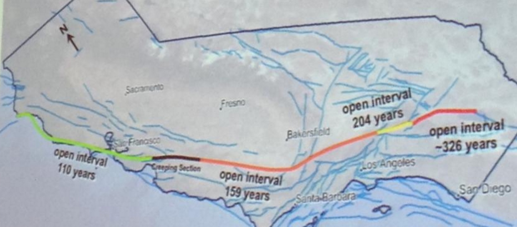
Believe it or not, Tom was not suggesting there is a gun pointed at our heads. ’Locked’ in seismic parlance means a fault is not freely slipping; ‘loaded’ means that sufficient stress has been reached to overcome the friction that keeps it locked. Tom argued that the San Andreas system accommodates 50 mm/yr (2 in/yr) of plate motion, and so with about 5 m (16 ft) of average slip in great quakes, the fault should produce about one such event a century. Despite that, the time since the last great quake (“open intervals” in the slide) along the 1,000 km-long (600 mi) fault are all longer, and one is three times longer. This is what he means by “ready to go.” Of course, a Mw=7.7 San Andreas event did strike a little over a century ago in 1906, but Tom seemed to be arguing that we should get one quake per century along every section, or at least on the San Andreas.
Could it be this simple?
Now, if things were so obvious, we wouldn’t need supercomputers to forecast quakes. In a sense, Tom’s wake-up call contradicted—or at least short-circuited—the case he so eloquently made in the body of his talk for building a vast inventory of plausible quakes in order to divine the future. But putting that aside, is he right about the San Andreas being ready to go?
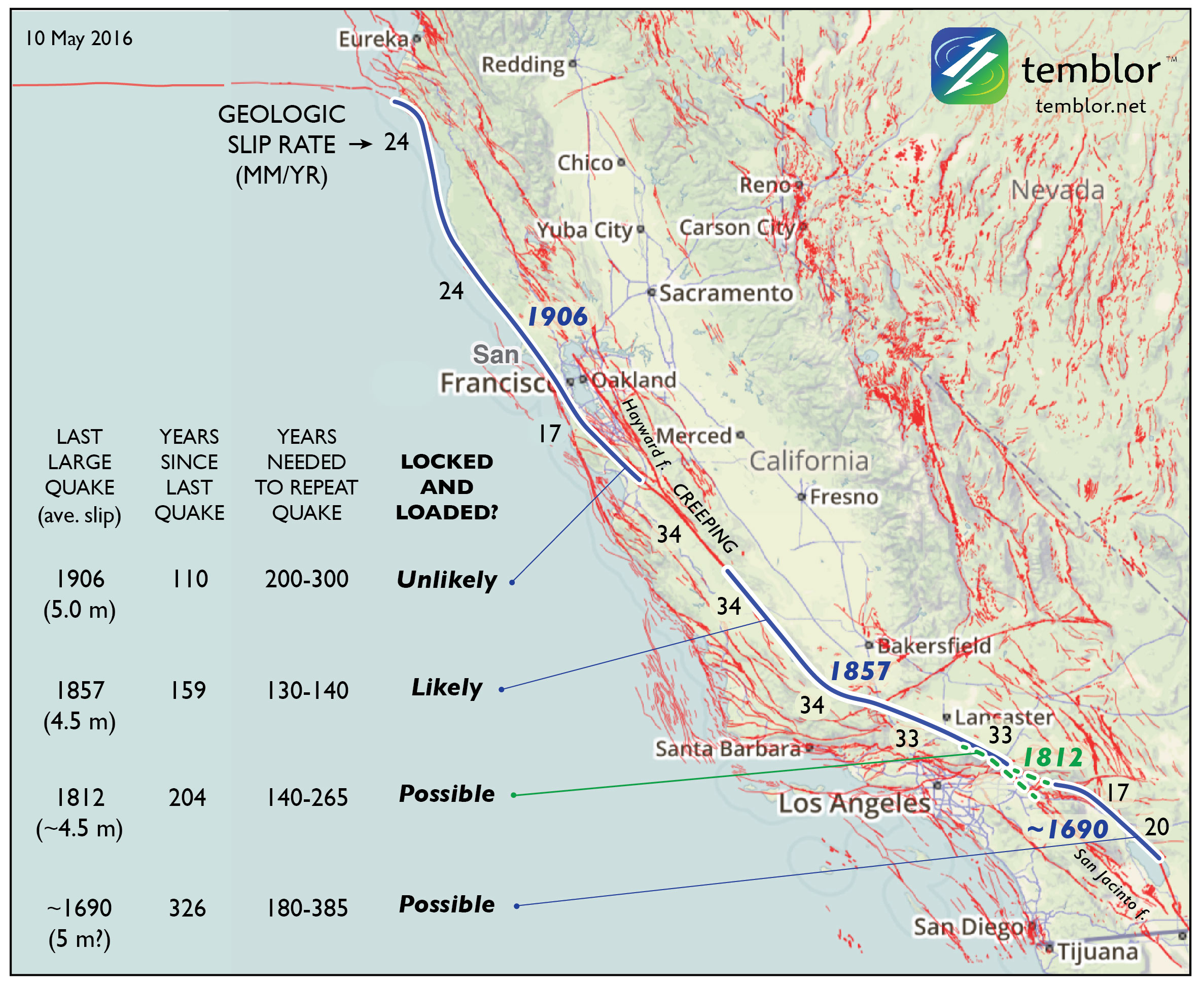
Because many misaligned, discontinuous, and bent faults accommodate the broad North America-Pacific plate boundary, the slip rate of the San Andreas is generally about half of the plate rate. Where the San Andreas is isolated and parallel to the plate motion, its slip rate is about 2/3 the plate rate, or 34 mm/yr, but where there are nearby parallel faults, such as the Hayward fault in the Bay Area or the San Jacinto in SoCal, its rate drops to about 1/3 the plate rate, or 17 mm/yr. This means that the time needed to store enough stress to trigger the next quake should not—and perhaps cannot—be uniform. So, here’s how things look to me:
So, how about ‘locked, generally loaded, with some sections perhaps ready to go’
When I repeat Tom’s assessment in the accompanying map and table, I get a more nuanced answer. Even though the time since the last great quake along the southernmost San Andreas is longest, the slip rate there is lowest, and so this section may or may not have accumulated sufficient stress to rupture. And if it were ready to go, why didn’t it rupture in 2010, when the surface waves of the Mw=7.2 El Major-Cucapah quake just across the Mexican border enveloped and jostled that section? The strongest case can be made for a large quake overlapping the site of the Great 1857 Mw=7.8 Ft. Teton quake, largely because of the uniformly high San Andreas slip rate there. But this section undergoes a 40° bend (near the ‘1857’ in the map), which means that the stresses cannot be everywhere optimally aligned for failure: it is “locked” not just by friction but by geometry.
A reality check from Turkey
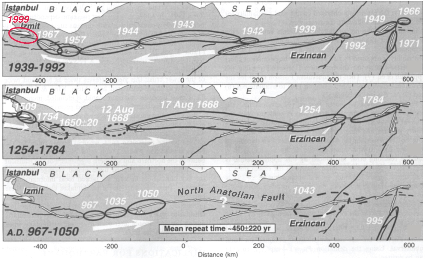
Sometimes simplicity is a tantalizing mirage, so it’s useful to look at the San Andreas’ twin sister in Turkey: the North Anatolian fault. Both right-lateral faults have about the same slip rate, length, straightness, and range of quake sizes; they both even have a creeping section near their midpoint. But the masterful work of Nicolas Ambraseys, who devoured contemporary historical accounts along the spice and trade routes of Anatolia to glean the record of great quakes (Nick could read 14 languages!) affords us a much longer look than we have of the San Andreas.
The idea that the duration of the open interval can foretell what will happen next loses its luster on the North Anatolian fault because it’s inter-event times, as well as the quake sizes and locations, are so variable. If this 50% variability applied to the San Andreas, no sections could be fairly described as ‘overdue’ today. Tom did not use this term, but others have. We should, then, reserve ‘overdue’ for an open interval more than twice the expected inter-event time.
However, another San Andreas look-alike, the Alpine Fault in New Zealand, has a record of more regular earthquakes, with an inter-event variability of 33% for the past 24 prehistoric quakes (Berryman et al., 2012). But the Alpine fault is straighter and more isolated than the San Andreas and North Anatolian faults, and so earthquakes on adjacent faults do not add or subtract stress from it. And even though the 31 mm/yr slip rate on the southern Alpine Fault is similar to the San Andreas, the mean inter-event time on the Alpine is longer than any of the San Andreas’ open intervals: 330 years. So, while it’s fascinating that there is a ‘metronome fault’ out there, the Alpine is probably not a good guidepost for the San Andreas.
If Tom’s slide is too simple, and mine is too equivocal, what’s the right answer?
I believe the best available answer is furnished by the latest California rupture model, UCERF3. Rather than looking only at the four San Andreas events, the team created hundreds of thousands of physically plausible ruptures on all 2,000 or so known faults. They found that the mean time between Mw≥7.7 shocks in California is about 106 years (they report an annual frequency of 9.4 x 10^-3 in Table 13 of Field et al., 2014; Mw=7.7 is about the size of the 1906 quake; 1857 was probably a Mw=7.8, and 1812 was probably Mw=7.5). In fact, this 106-year interval might even be the origin of Tom’s ‘once per century’ expectation since he is a UCERF3 author.
But these large events need not strike on the San Andreas, let alone on specific San Andreas sections, and there are a dozen faults capable of firing off quakes of this size in the state. While the probability is higher on the San Andreas than off, in 1872 we had a Mw=7.5-7.7 on the Owen’s Valley fault (Beanland and Clark, 1994). In the 200 years of historic records, the state has experienced up to three Mw≥7.7 events, in southern (1857) and eastern (1872), and northern (1906) California. This rate is consistent with, or perhaps even a little higher than, the long-term model average.
So, what’s the message
While the southern San Andreas is a likely candidate for the next great quake, ‘overdue’ would be over-reach, and there are many other fault sections that could rupture. But since the mean time between Mw≥7.7 California shocks is about 106 years, and we are 110 years downstream from the last one, we should all be prepared—even if we cannot be forewarned.
Ross Stein (ross@temblor.net), Temblor
You can check your home’s seismic risk at Temblor
References cited:
Sarah Beanland and Malcolm M. Clark (1994), The Owens Valley fault zone, eastern California, and surface faulting associated with the 1872 earthquake, U.S. Geol. Surv. Bulletin 1982, 29 p.
Kelvin R. Berryman, Ursula A. Cochran, Kate J. Clark, Glenn P. Biasi, Robert M. Langridge, Pilar Villamor (2012), Major Earthquakes Occur Regularly on an Isolated Plate Boundary Fault, Science, 336, 1690-1693, DOI: 10.1126/science.1218959
James H. Dietrich and Keith Richards-Dinger (2010), Earthquake recurrence in simulated fault systems, Pure Appl. Geophysics, 167, 1087-1104, DOI: 10.1007/s00024-010-0094-0.
Edward H. (Ned) Field, R. J. Arrowsmith, G. P. Biasi, P. Bird, T. E. Dawson, K. R., Felzer, D. D. Jackson, J. M. Johnson, T. H. Jordan, C. Madden, et al.(2014). Uniform California earthquake rupture forecast, version 3 (UCERF3)—The time-independent model, Bull. Seismol. Soc. Am. 104, 1122–1180, doi: 10.1785/0120130164.
Robert Graves, Thomas H. Jordan, Scott Callaghan, Ewa Deelman, Edward Field, Gideon Juve, Carl Kesselman, Philip Maechling, Gaurang Mehta, Kevin Milner, David Okaya, Patrick Small, Karan Vahi (2011), CyberShake: A Physics-Based Seismic Hazard Model for Southern California, Pure Appl. Geophysics, 168, 367-381, DOI: 10.1007/s00024-010-0161-6.
Julian C. Lozos (2016), A case for historical joint rupture of the San Andreas and San Jacinto faults, Science Advances, 2, doi: 10.1126/sciadv.1500621.
Tom Parsons, K. M. Johnson, P. Bird, J.M. Bormann, T.E. Dawson, E.H. Field, W.C. Hammond, T.A. Herring, R. McCarey, Z.-K. Shen, W.R. Thatcher, R.J. Weldon II, and Y. Zeng, Appendix C—Deformation models for UCERF3, USGS Open-File Rep. 2013–1165, 66 pp.
Seok Goo Song, Gregory C. Beroza and Paul Segall (2008), A Unified Source Model for the 1906 San Francisco Earthquake, Bull. Seismol. Soc. Amer., 98, 823-831, doi: 10.1785/0120060402
Kerry E. Sieh (1978), Slip along the San Andreas fault associated with the great 1857 earthquake, Bull. Seismol. Soc. Am., 68, 1421-1448.
Ross S. Stein, Aykut A. Barka, and James H. Dieterich (1997), Progressive failure on the North Anatolian fault since 1939 by earthquake stress triggering, Geophys. J. Int., 128, 594-604, 1997, 10.1111/j.1365-246X.1997.tb05321.x

Impact Community Resilience as a USRC Member and Certified Rater
The U.S. Resiliency Council (USRC) recently launched its Building Rating System for earthquake hazards. The Rating System assigns a score of from one to five stars for three building performance measures: Safety, Damage (repair cost) and Recovery (time to regain basic function).Continue Reading

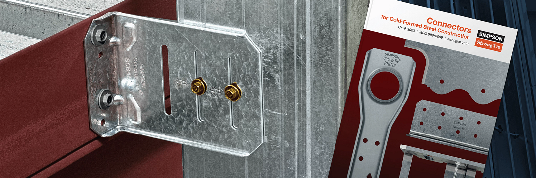
24th Short Course on CFS Structures: October 27-29 in St. Louis
Simpson Strong-Tie is sponsoring the 24th Short Course on Cold-Formed Steel Structures hosted by the Wei-Wen Yu Center for Cold-Formed Steel Structures (CCFSS). The course will be held on October 27-29, 2015 at the Drury Plaza Hotel at the Arch in St. Louis, MO.
This three-day course is for engineers who have limited or no experience designing with cold-formed steel (CFS), as well as those with experience who would like to expand their knowledge of cold-formed steel structural design. Lectures will be given by industry-recognized experts Roger LaBoube, Ph.D., P.E., and Sutton Stephens, Ph.D., P.E., S.E. The course is based on the 2012 AISI North American Specification for the Design of Cold-Formed Steel Structural Members and the 2012 North American Standards for Cold-Formed Steel Framing. Dr. Wei-Wen Yu’s book Cold-Formed Steel Design (4th Edition) will be a reference text.
The course will address such topics as design of wall studs, floor joists, purlins, girts, decks and panels. It is eligible for 2.4 Continuing Education Units (CEUs). Advance registration is requested by October 10, 2015. For more information and to register, click here.

BRACE FOR IMPACT! Bracing Design for Cold-Formed Steel Studs
While consideration of bracing is important for any structural element, this is especially true for thin, singly symmetric cold-formed steel (CFS) framing members such as wall studs. Without proper consideration of bracing, excessive buckling or even failure could occur. Bracing is required to resist buckling due to axial or out-of-plane lateral loads or a combination of the two.
There are two methods for bracing CFS studs as prescribed by the American Iron and Steel Institute (AISI) Committee on Framing Standards (COFS) S211 “North American Standard for Cold-Formed Steel Framing – Wall Stud Design” Section B1. One is sheathing braced design and the other is steel braced design.
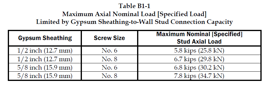
Sheathing braced design has limitations, but it is a cost effective method of bracing studs since sheathing is typically attached to wall studs. This design method is based on an assumption that the sheathing connections to the stud are the bracing points and so it’s limited by the strength of the sheathing fastener to stud connection. Due to this limitation, the Designer has to use a steel braced design for most practical situations. AISI S211 prescribes a maximum nominal stud axial load for gypsum board sheathing with fasteners spaced no more than 12 inches on center. AISI S211 Section B1 and the Commentary discuss the design method and assumptions and demonstrate how to determine the sheathing bracing strength.
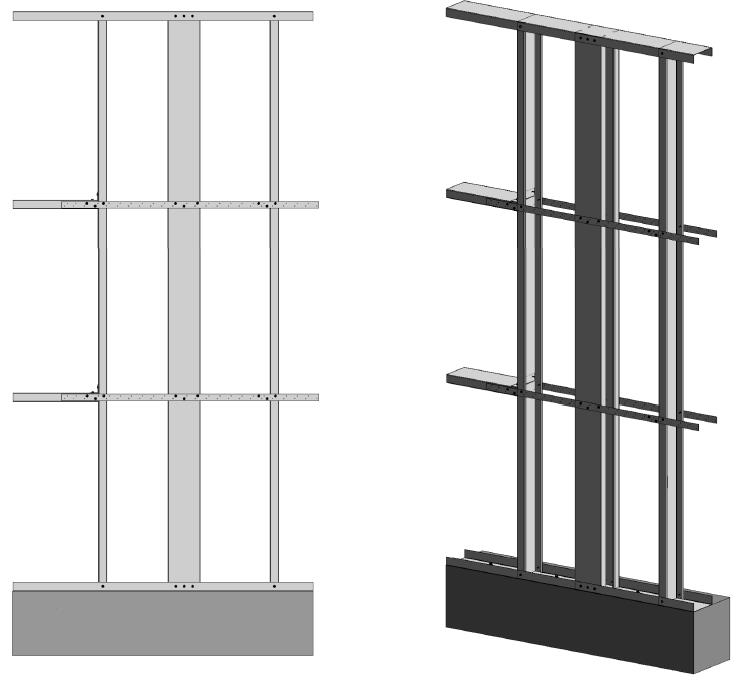
Sheathing braced design requires that identical sheathing is used on each side of the wall stud, except the new AISI S240 standard Section B1.2.2.3 clarifies that for curtain wall studs it is permissible to have sheathing on one side and discrete bracing for the other flange not spaced further than 8 feet on center. The wall stud is connected to the top and bottom tracks or supporting members to provide lateral and torsional support and the construction drawings should note that the sheathing is a structural element. When the sheathing on either side is not identical, the Designer must assume the weaker of the two sheathings is attached to each side. In addition, the Designer is required to design the wall studs without the sheathing for the load combination 1.2D + (0.5L or 0.2S) + 0.2W as a consideration for construction loads of removed or ineffective sheathing. The Designer should neglect the rotational restraint of the sheathing when determining the wall stud flexural strength and is limited by the AISI S100 Section C5.1 interaction equations for designing a wall stud under combined axial and flexural loading.
Steel braced design may use the design methodology shown in AISI S211 or in AISI Committee on Specifications (COS) S100 “North American Specification for the Design of Cold-Formed Steel Structural Members.”
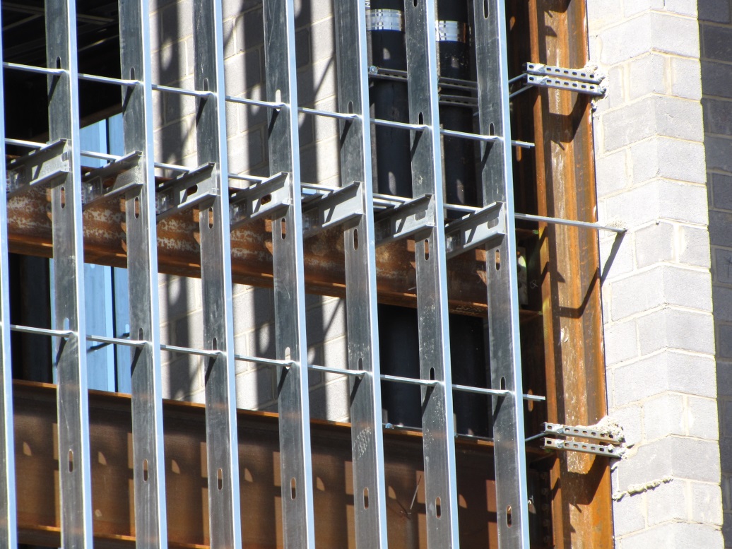
Steel braced design is typically either non-proprietary or proprietary “clip and bridging” bracing, or “flat strap and blocking” bracing periodically spaced along the height of the wall stud.

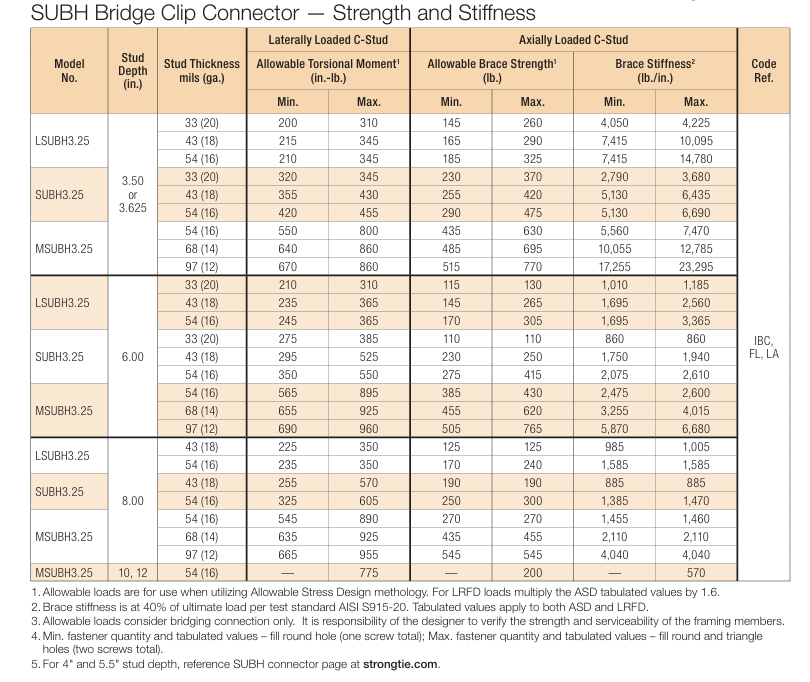
Proprietary wall bracing and wall stud design solutions can expedite design with load and stiffness tables and software as well as offer efficient, tested and code-listed solutions such as Simpson Strong-Tie wall stud bridging connectors.
Steel braced design is a more practical bracing method for several reasons. First, during construction, wall studs go unsheathed for many months, but are subjected to significant construction loads.This is especially true for load-bearing, mid-rise structures. Second, some sheathing products, including gypsum wallboard, can be easily damaged and rendered ineffective if subjected to water or moisture. Third, much higher bracing loads can be achieved using mechanical bracing. IBC Section 2211.4 permits Designers to design steel bracing for axially loaded studs using AISI S100 or S211. However, S100-07 requires the brace to be designed to resist not only 1% of the stud nominal axial compressive strength (S100-12 changes this to 1% of the required compressive axial strength), but also requires a certain brace stiffness. S211 requires the Designer to design the bracing for 2% of the stud design compression force, and it does not have a stiffness requirement. . AISI S100 is silent regarding combined loading, but S211 provides guidance. S211 requires that, for combined loading, the Designer designs for the combined brace force determined using S100 Section D3.2.1 for the flexural load in the stud and either S100 or S211 for the axial load. In addition, the bracing force for stud bracing is accumulative as stated by S211 Commentary section B3. As a result, the periodic anchorage of the bracing to the structure such as strongbacks or diagonal strap bracing is required.
Some benefits and challenges of steel clip and bridging bracing include:
- Proprietary solutions, such as the Simpson Strong-Tie SUBH bridging connector, can significantly reduce installed cost since many situations require only one screw at each connection.
- Unlike strap bracing, u-channel bracing can be installed from one side of the wall.
- U-channel bracing does not create build-up that can make drywall finishing more difficult.
- Extra coordination may be required to ensure that u-channel bridging does not interfere with plumbing and electrical services that run vertically in the stud bay.
- Bracing for axial loaded studs requires periodic anchorage to the structure, such as using strongbacks or diagonal strap bracing.
- Bracing of laterally loaded studs does not require periodic anchorage since the system is in equilibrium as torsion in the stud is resisted by bridging (e.g., U-channel) bending.
Some benefits and challenges of steel flat strap and blocking bracing include:
- May be installed at other locations than stud punchout.
- Required to be installed on both sides of wall.
- Bumps out sheathing.
- Bracing for axial loaded studs requires periodic anchorage to structure, such as using strongbacks or diagonal strap bracing (same load direction in stud flanges).
- Bracing for laterally loaded studs requires design of periodic blocking or periodic anchorage to the structure (opposite load direction in stud flanges).
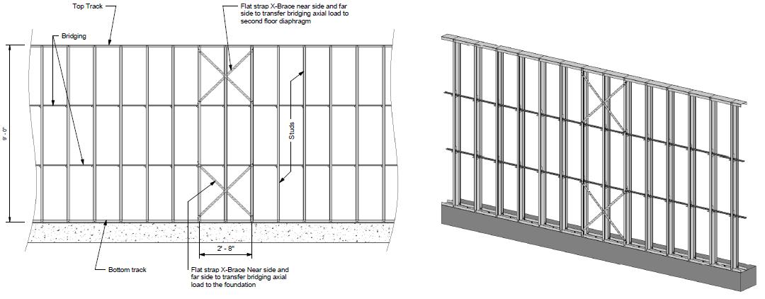
There are several good examples Designers may reference when designing CFS wall stud bracing. They include AISI D110 Cold-Formed Steel Framing Design Guide that may be purchased from www.cfsei.org, SEAOC Structural/Seismic Design Manual Volume 2 Example 3 that may be purchased from www.seaoc.org, and the Simpson Strong-Tie wall stud steel bracing design example on page 147 of the C-CF-2026 CFS catalog.
Cold-formed steel framing is a versatile construction material, but Designers need to carefully consider the bracing requirements of the AISI specification and wall stud design standard. What cold-formed steel wall bracing challenges have you encountered and what were your solutions?

What Factors Contribute To A “Resilient” Community?
The world has seen many increasingly catastrophic natural disasters in the past decade, including Hurricane Katrina (Category 3) striking New Orleans in 2005, 2010’s 7.0 magnitude Haiti and 8.8 magnitude Chili earthquakes, the 9.0 magnitude Japan earthquake along with the Christchurch earthquake (6.3 magnitude) in 2011, the tornado outbreak in 2011 which included an EF4 striking Tuscaloosa, AL and a multiple-vortex EF5 striking Joplin, MO. We also saw Category 2 Hurricane Sandy, the largest Atlantic hurricane on record in 2012 and the EF5 tornado striking Moore, Oklahoma in 2013.

Midrise of Steel

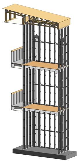
The number of midrise structures constructed using light-frame cold-formed steel (CFS) certainly seems to be increasing each year. As with any material, there are benefits and challenges, especially in areas of moderate to high seismic risk. This post will discuss these as well as potential solutions.
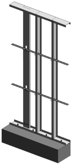
Light-frame CFS midrise construction often uses ledger floor framing primarily to facilitate the load transfer detailing at the floor, tension anchorage (tie-downs or hold-downs) and compression chord studs or posts designed to resist the amplified seismic overturning loads. CFS framing is typically thin and singly symmetric.

Amplified Seismic Load
The AISI Lateral Design standard (AISI S213-07/S1-09) Section C5.1.2 requires that the nominal strength of uplift (tension) anchorage and the compression chord studs for shear walls resist the lesser of (1) the amplified seismic load or (2) the maximum load the system can deliver when the response modification coefficient, R, greater than 3. The amplified seismic load is defined as the load determined using the ASCE 7 seismic load combinations with the overstrength factor, Wo, which may be taken as 2.5 for CFS framed shear wall systems with flexible diaphragms.
Typically, the maximum the system can deliver to the uplift anchorage or chord studs is taken as the forces determined using the nominal shear strength of the shear wall assembly tabulated in the seismic shear wall table in S213 multiplied by 1.3. The S213 commentary accounts for the tabulated loads being based on Sequential Phased Displacement (SPD) rather than CUREE cyclic protocol and the degraded backbone curve. See the Structure magazine article that discusses the design of CFS framed lateral force-resisting systems.
Continuous Rod Tie-Down Systems
Light-framed CFS over three stories often use continuous rod tie-down systems rather than cold-formed steel hold-downs to resist shear wall overturning forces as they offer increased load capacity. Neglecting the dead load contribution, the amplified seismic load requirement for CFS shear walls using an R greater than 3 results in an 80% increase in the load used to size the continuous rod tie-down system compared to design level loads. For shear walls using an R greater than 3, it is important to note on the design drawings whether the uplift loads shown are ASD, LRFD, amplified ASD or amplified LRFD so the appropriate tie-down system may be designed.
Continuous rod tie-down systems are designed not only for strength, but also checked to ensure they do not deflect too much to cause the top of shear wall drift to exceed the code limit or to exceed the 0.20” vertical story deflection limit required by some jurisdictions and ICC-ES AC316. Take-up devices are used in CFS framed structures to take-up construction and settlement gaps that may occur. AISI S200 Section C3.4.4 states that a gap of up to 1/8” might occur between the end of wall framing and the track. The vertical elongation of the continuous rod tie-down system includes rod elongation (PL/AE) and the take-up device deflection due to the seating increment and the deflection under load.
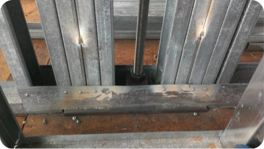
In addition, coordination is important in using continuous rod tie-down systems in CFS structures because the walls are often prefabricated offsite. An example is the consideration of the appropriate detail for the steel bearing plate installed at the floor sheathing in the story above to resist the uplift (tension) force from the story below.
One possible detail is to install the bearing plate in the bottom CFS track under all the CFS chord studs, but it’s important to ensure the bottom track flanges are deep enough to screw them to the stud flanges as the bearing plate can have a thickness of 1 ½” or more and typical tracks use 1 ¼” flanges. It is also important to ensure that the bearing plate width fits in the track. Another possible detail is to install the bearing plate under the CFS track under all the CFS chord studs. However, then it must be cut into the floor sheathing and may cause the bottom track to be raised at the bearing plate. For this detail, the floor shear transfer must be detailed through the ledger into the CFS framing.
Concrete Tension Anchorage
The concrete tension anchorage is designed according to ACI 318 Appendix D using the continuous steel rod material and size in accordance with S213 to have the nominal strength to resist the lesser of the amplified seismic force or the maximum load the system can deliver. ACI 318-11 Section D.3.3.4.3 offers four force limits for design of concrete tension anchorage design in Seismic Design Category C through F:
(1) The concrete nominal tension anchorage strength shall be greater than 1.2 times the ductile steel rod nominal tension anchorage strength
(2) The anchorage design strength shall be greater than the maximum tension force that can be delivered by a yielding attachment;
(3) The anchorage design strength shall be greater than the maximum tension force that can be delivered by a non-yielding attachment; and
(4) The anchorage design strength shall be greater than the amplified seismic force.
Typically either option (1) or (4) is used where (1) would lead to less concrete required than (4) if the bolt is efficiently sized while (4) would be required for such conditions as a vertical irregularity. See the concrete anchorage and podium anchorage SE Blog posts for more details.

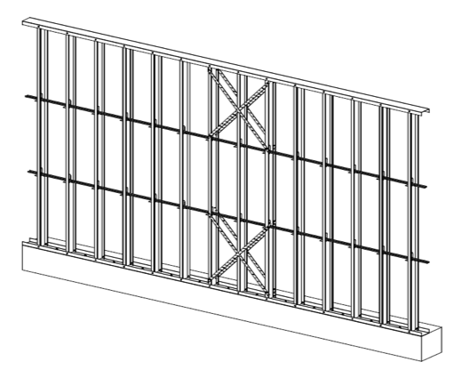
CFS Wall Stud Bracing
CFS studs are typically thin and singly symmetric and thus require bracing. AISI S211 (Wall Stud Design Standard) permits two types of bracing design that cannot be combined; sheathing based or steel based. There are limits on the stud axial strength when using sheathing braced design. It’s important to identify on the drawings that the sheathing braces the studs and another load combination must be used for the stud design.
2012 IBC Section 2211.4 requires stud bracing to be designed using either AISI S100 (North American Specification) or S211 (Wall Stud Design Standard). S100-07 Section D3.3 required nominal brace strength is to be 1% of the stud’s nominal compressive axial strength, but S100-12 Section D3.3 changes this to the required brace strength is to be 1% of the stud’s required compressive axial strength (demand load). In addition, D3.3 requires a certain stiffness for each brace. AISI S211 required brace strength is to be 2% of each stud’s required compressive axial strength for axially loaded studs and, for combined bending and axial loads, be designed for the combined brace force per S100 Section D3.2.2 and 2% of the stud’s required compressive axial strength.
There are two primary types of steel stud bracing systems: bridging and strap bracing. U-channel bridging extends through the stud punchouts and is attached to the stud with a clip, of which there are various solutions such as this post on Wall Stud Bridging. Bridging bracing requires coordination with the building elements in the stud bay. It installs on one side of the wall, and does not bump out the wall sheathing. It also requires periodic anchorage to distribute the cumulative bracing loads to the structure for axially loaded studs often using strongback studs and does not require periodic anchorage for laterally loaded studs since the system is in equilibrium as the torsion in the stud is resisted by the U-channel bending.
Flat strap bracing is installed on either side of the wall and at locations other than the stud punchout. It bumps out the sheathing and requires periodic anchorage to distribute the cumulative bracing loads to the structure for axially and laterally loaded studs.
![]()

![]()
Light-frame cold-formed steel construction has been used successfully for many projects, but there are challenges that must be addressed to ensure code compliance and desired performance. Some beneficial resources for designing CFS structures are the SEAOC 2012 IBC Structural/Seismic Design Manual Volumes 1 and 2 and the Cold-Formed Steel Engineers Institute’s (CFSEI) website where you can find technical notes and design guides.
What have been some of your observations or challenges in designing cold-formed steel midrise structures?