This is Part 1 of a four-part series I’ll be doing on how connectors, fasteners, anchors and cold-formed steel systems are load rated.
Today I did my presentation for the WoodWorks webinar on Testing and Product Evaluation of Products for Wood-framed Construction. We covered a lot of material regarding code requirements for using alternate materials or construction methods, how testing and evaluation criteria are developed, and some specifics on several Acceptance Criteria (AC’s) that are commonly used for connector evaluations. We also discussed some specific testing requirements, so I thought it would be timely to discuss some of those issues in this week’s blog post.
So, how are structural connectors for light frame wood construction load rated? What’s behind the allowable loads information published in Simpson Strong-Tie literature or wood connector evaluation reports? These are things that you might find yourself wondering while driving to the office or jobsite, or on a Sunday afternoon while enjoying your favorite iced tea or barley-based beverage.
The short answer is: testing, calculations, and of course, sound engineering judgment.
The International Building Code (IBC) contains specific requirements that are used to determine the allowable load of a structural connector in Section 1711.2, and the International Residential Code (IRC) states that approved connectors may be used provided they meet the intent of the code. In addition, ASTM standards and approved acceptance criteria, which dive further into the nuts and bolts of connector testing and results analysis, are referenced.
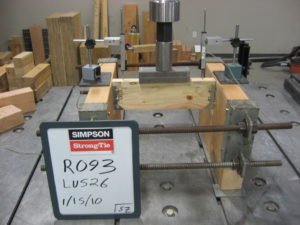
The IBC states that at least three specimens shall be tested in order to determine the allowable load of a structural connector used in wood construction. For our purposes, a specimen is a test assembly that has been constructed with the intent of approximating field conditions for a given connection type. In the case of joist hangers, an assembly is constructed using two simulated header beams with a joist supported by the tested hanger. For hurricane ties, the assembly is constructed using simulated double 2x top plates and a rafter or truss member connected with a hurricane tie.
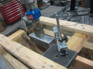
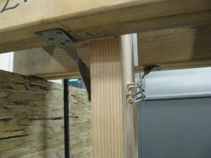
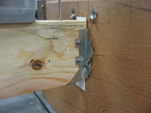
It is a little harder to visualize lateral load tests of hurricane ties since we turn everything sideways to apply the loads. In the first photo you can see the two sets of double 2x top plates and the 2×10 that is simulating the joist or rafter. The actuator will push down on the end of the 2×10 to simulate a lateral (F2 direction) load. Second photo you can see where the H2.5As are installed.
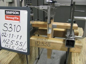
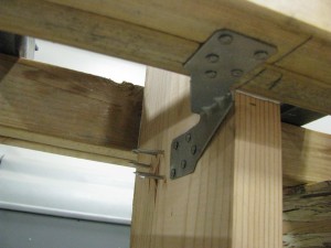
For this post, we’ll skip discussing holdown testing or setup requirements. The acceptance criteria for holdowns has some more detailed testing requirements and specific reasons for those requirements that warrant a separate blog post.
Strength and stiffness are important connection performance characteristics. The allowable load from testing considers limits associated with each characteristic and is based on the lower of the two. The value derived from the strength limit criterion is taken as the lowest ultimate load of three tests (or average of six) divided by a safety factor of 3. The deflection limit is based on the average load of three tests that corresponds to ⅛” of relative test member movement.
Once testing is complete, calculations are the final component used to determine the connection’s allowable load. Calculations are performed in accordance with the National Design Specification for Wood Construction (NDS), and may include considerations for fastener shear, fastener withdrawal, and/or member bearing based on the load path inherent to a particular connection type.
The lowest value achieved from testing and determined through calculations may be considered the allowable load for the connection. This is the value that you would see in any wood connection allowable load table in our literature or an evaluation report.
See for yourself.
What are your thoughts? Visit the blog and leave a comment.
– Paul
What are your thoughts? Visit the blog and leave a comment!


Is there a different safety factor used for individual fasteners verses a tested assembly using several fasteners?
In NDS commentary on fasteners they reference a safety factor of 4.
In IBC 1714 for pre-construction load tests a safety factor of 2.5 is required.
In IBC 1713 for in situ load tests a load factor of 2 is required.
Yes, the safety factor for fasteners tested under AC233 – Acceptance Criteria For Alternate Dowel-Type Threaded Fasteners, the safety factor on individual fasteners is 5. If you were to test nails, AC116 – Acceptance Criteria For Nails and Spikes, uses a safety factor of 5 also.