

This is Part 1A of a four-part series I’ll be doing on how connectors, fasteners, anchors and cold-formed steel systems are load rated.
I envisioned doing a four-part series on how connectors, fasteners, anchors, and cold-formed steel are load rated. After writing the first installment on connectors, I realized that connectors are a bit more complicated, since the testing and evaluation for joist hangers (or similar devices) is different than testing for holdown devices. And I wanted to discuss holdowns. So without belaboring the apology for my numbering system, this will be part 1A of the series – still discussing wood connectors, but focusing on holdowns and some of the unique requirements in their load rating.
AC155, Acceptance Criteria for Hold-Downs (Tie-Downs) Attached to Wood Members, was first developed in 2005 to better address boundary conditions, deflection limits, and wood post limits. Prior to AC155, holdowns were evaluated based on testing on a steel jig with a safety factor of 3.0 and an NDS bolt calculation. Deflection at the allowable load was simply reported so that it was available for use in design, but there was not a deflection limit that affected the load rating.
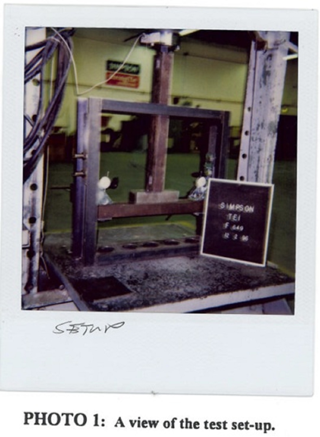
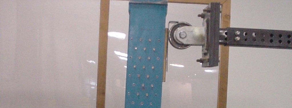
In the steel jig setup shown, the jig keeps the holdowns stationary while the rectangular bar underneath the holdowns is pushed downward to simulate an uplift force. This was (and still is) an effective method of testing the capacity of the steel body of a holdown, but it does not tell you a lot about the deflection of the holdown when installed on a wood member. Since story-drift is such a critical component to shearwall performance and the deflection of holdowns has a significant effect on the total drift, this needed to be address in the holdown test standard.
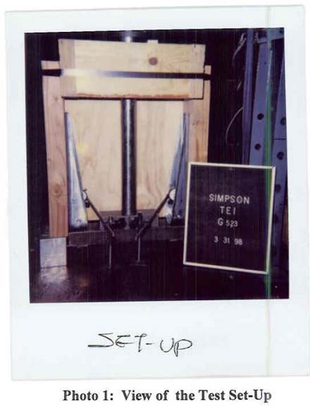
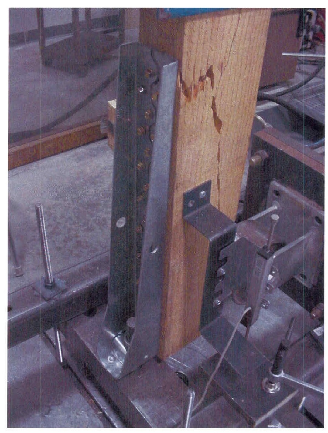
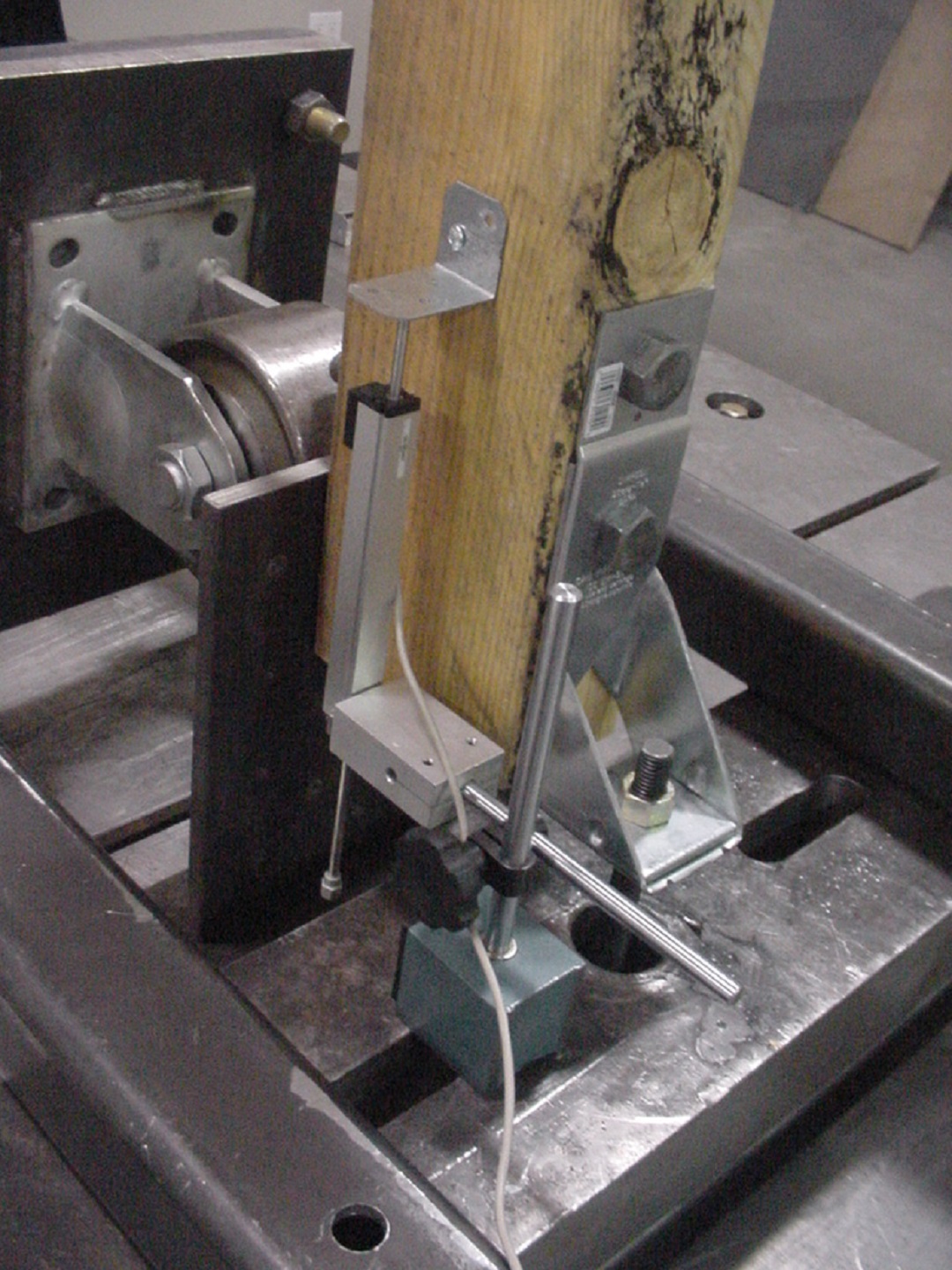
The wood jig test setup used for screw style holdowns is an improvement, since the holdown is tested on wood. However, the setup shown will load the post in compression. Having the post end grain bearing on the test bed eliminates several possible failure modes one might observe if the post is loaded in tension.
The critical requirements found in AC155 are:
(1) Deflection limits based on assembly tests on wood members
(2) Test setup to match the intended use (i.e., load the post in tension for a holdown)
(3) Steel jig testing to evaluate strength of the holdown
There are some slight differences when evaluating nailed or screw style holdowns and bolted holdowns, which are outlined below:
| Nailed/Screwed Holdowns: | Bolted Holdowns: |
| Fastener Calculation | Faster Calculation |
| Deflection Limits: | Deflection Limits: |
| ¼” Deflection Limit on Wood Post | ¼” Deflection Limit on Wood Post |
| 0.185” Deflection Limit on Steel Jig | 0.185” Deflection Limit on Steel Jig |
| Deflection Limits at Strength Levels | Deflection Limits at Strength Levels |
| Ultimate Load Limit | Ultimate Load Limit |
| Steel Jig Test ÷ 2.5 | Steel Jig Test ÷ 2.5 |
| Wood Assembly Test ÷ 3.0 |

Since shearwall deflections are calculated at strength levels, the deflection limits are also at strength level. To convert to allowable stress design numbers, you divide the deflection limited load by 1.4 and the corresponding deflection is measured from the average load-deflection curve. In addition to a steel jig test limit, nailed and screwed holdowns have an ultimate load limit based on the wood assembly test. This requirement is included to evaluate potential wood failures around the fasteners.
What are your thoughts? Visit the blog and leave a comment.
– Paul
What are your thoughts? Visit the blog and leave a comment!

Thanks for the info. I’ve been looking for calgary fasteners for a while