

Last week’s post reviewed some of the common questions WoodWorks receives from engineers designing five-story, Type III wood-frame buildings—including those related to fire retardant-treated building elements, and fire-rated floor and wall assemblies. This week, we extend that conversation to another common issue—details and fire rating of floor-to-wall intersections.
The fire rating of an exterior wall assembly in Type III construction causes a detailing issue where the floor intersects the exterior wall assembly. There are no testing criteria established by the code for system intersections of any material, so detailing must rely on code interpretation. The two points of interpretation focus on continuity of the two-hour wall fire rating and the FRT requirement.
Section 705.6 of the 2012 IBC 1 requires that an exterior wall have “sufficient structural stability such that it will remain in place for the duration of time indicated by the required fire resistance rating.” The ‘interruption’ of the floor in the plane of the exterior wall may be seen by authorities as affecting the structural stability. It is not clear how designers are to comply with this language; for that reason, the language has been removed in the 2015 IBC.
The implication of FRT continuity is derived from the primary requirement that Type III buildings have noncombustible exterior walls. FRT wood is permitted in these walls per IBC Sections 602.3 and 602.4. Since the noncombustibility or acceptable FRT alternative is intended to reduce fire exposure to other buildings, some code officials require FRT material in the plane of exterior walls through the floor intersection. The degree to which a building official believes that the rim joist, floor joist and/or sheathing present a risk of fire spread will determine the degree of FRT material required through the floor-wall intersection.
The manner in which this floor-to-wall connection can be detailed first depends on the type of framing being used—traditional platform framing or semi/modified balloon framing. Platform framing relies on the fact that the floor system bears directly onto the wall below. Semi-balloon framing relies on hangers to support the floor framing.
Typical platform-framed floor-to-wall intersections have been accepted by many jurisdictions without any special detailing according to the rationale that the area of intersection represents “floor framing” and not “wall framing.” In these intersections, the “floor” is not required to be FRT and its fire resistance is limited to one hour. This is similar to the floor conditions found in Type V construction; where such conditions obtain, it’s also logical to extend the same detailing allowances at this intersection to Type III buildings.
While local code interpretation varies widely, a variety of detailing concepts have arisen across the country as possible solutions to this issue.
In one solution, a solid sawn, glulam or engineered rim board is used to create continuity of the two-hour rating through the plane of the wall by using the charring capability of the rim board calculated using Chapter 16 of the NDS. Variations of this detail include a built-up rim board. In some solutions, the member closest on the outside of the wall may also be FRT to provide some degree of FRT continuity. If continuity of FRT through the floor for the entire width of the wall is also required, the entire thickened rim board and possibly the first sheet of floor sheathing may need to be FRT. In some scenarios without heavy FRT requirements, a hanger is not needed if the rim board width that can accommodate the charring is narrower than the width of the wall and the joist can bear on the top plate itself.
Another option is to use a continuous 2x block to achieve one hour of fire resistance, again calculated using Chapter 16 of the NDS. The second hour of resistance is provided by the horizontally applied drywall on the underside of the floor. While the two layers of drywall may not be in the plane of the wall, they still provide two hours of fire endurance. This detail may or may not require that the block and the floor sheathing be FRT, depending on the FRT continuity interpretation. Variations of this detail include an option where the blocking is moved inside the plane of the wall between the joists. Some jurisdictions object, citing concerns about fires starting in the floor cavity. There are other measures, such as fire blocking or cavity sprinklers, provided to minimize spread of fire in these situations. The same question could be asked about fires starting within a wall cavity.
A third option is a slight variation of the second. Instead of using blocking to achieve the one hour of fire resistance, one layer of drywall can extend up behind certain proprietary top flange joist hangers (for SST example, click here). This provides one hour of fire resistance in the plane of the wall, and the second hour is provided by the drywall on the underside of the floor. Some contractors find this detail difficult to accommodate because of construction sequencing — the drywall crew typically does not arrive on site until after rough framing is complete. A variation seen in some areas is using a top-chord-bearing truss, which eliminates the hanger hardware and minimizes the non-treated penetration in the plane of the exterior wall. Addressing full FRT continuity may be more difficult with this variation depending on the truss manufacturer.
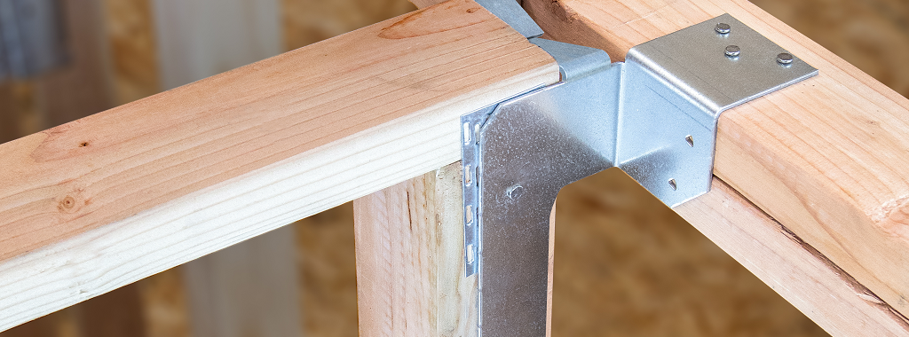
A fourth option requires relatively new concepts using connector solutions that allow two layers of gypsum to be applied behind the floor joist connection to the wall (for SST example, click here). Hardware solutions can be a useful option to have available when an Authority Having Jurisdiction is particularly wary of maintaining the integrity of a rated wall assembly, but Designers should consider both the labor and the cost of these details to determine the best fit for the project.
In addition to regional nuances and differing (and evolving) code interpretations, there isn’t one solution that fits all applications. Designers should determine the local availability of FRT products, review manufacturer product specifications and discuss the proposed solution with their jurisdiction.
Available Support
If you’re designing a mid-rise wood building and have questions—e.g., about fire and life safety, lateral and vertical loads, how to address shrinkage, etc.—I encourage you to contact your local WoodWorks regional director. The WoodWorks website (woodworks.org) also offers a wide range of technical information on mid-rise structures and we welcome inquiries to the project assistance help desk (help@woodworks.org).
1Information is based on the 2012 International Building Code unless otherwise indicated.
