As published in STRUCTURE magazine, September 2016. Written by Randy Daudet, P.E., S.E., Product Manager at Simpson Strong-Tie. Re-posted with permission.
One of the world’s greatest unsolved mysteries of our time lies in a courtyard outside of the Central Intelligence Agency (CIA) headquarters in Langley, Virginia. It’s a sculpture called Kryptos, and although it’s been partially solved, it contains an inscription that has puzzled the most renowned cryptanalysts since being erected in 1990. Meanwhile, in another part of the DC Beltway about 15 miles to the southeast, another great mystery is being deciphered at the American and Iron Institute (AISI) headquarters.
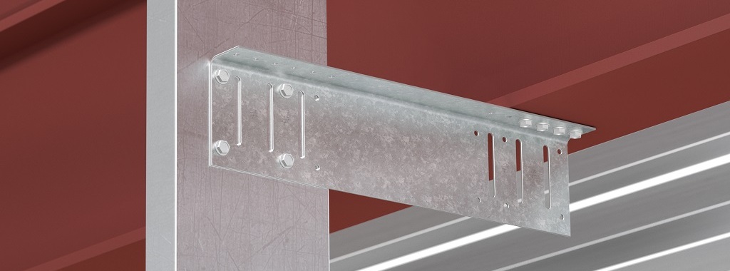
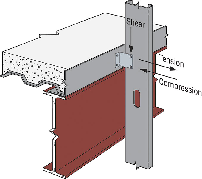
The mystery, structural behavior of cold-formed steel (CFS) clip angles, has puzzled engineers since the great George Winter helped AISI publish its first Specification in 1946. In particular, engineers have struggled with how thin-plate buckling behavior influences CFS clip angle strength under shear and compression loads. Additionally, there has been considerable debate within the AISI Specification Committee concerning anchor pull-over strength of CFS clip angles subject to tension.
The primary problem has been the lack of test data to explain clip angle structural behavior. Even with modern Finite Element Analysis (FEA) tools, without test data to help establish initial deformations and boundary conditions, FEA models have proven inaccurate. Fortunately, joint funding provided by AISI, the Steel Framing Industry Association (SFIA), and the Steel Stud Manufactures Association (SSMA) has provided the much-needed testing that has culminated in AISI Research Report RP15-2, Load Bearing Clip Angle Design, that summarizes phase one of a multi-year research study. The report summarizes the structural behavior and preliminary design provisions for CFS load bearing clip angles and is based on testing that was carried out in 2014 and 2015 under the direction of Cheng Yu, Ph.D. at the University of North Texas. Yu’s team performed 33 tests for shear, 36 tests for compression, and 38 tests for pull-over due to tension. Clip angles ranged in thickness from 33 mils (20 ga.) to 97 mils (12 ga.), with leg dimensions that are common to the CFS framing industry. All of the test set-ups were designed so that clip angle failure would preclude fastener failure.
For shear, it was found that clips with smaller aspect ratios (L/B < 0.8) failed due to local buckling, while clips with larger aspect ratios failed due to lateral-torsional buckling. Shear test results were compared to the AISC Design Manual for coped beam flanges, but no correlation was found. Instead, a solution based on the Direct Strength Method (DSM) was employed that utilized FEA to develop a buckling coefficient for the standard critical elastic plate-buckling equation. Simplified methods were also developed to limit shear deformations to 1/8 inch. For compression, it was found that flexural buckling was the primary failure mode. Test results were compared to the gusset plate design provisions of AISI S214, North American Standard for Cold-Formed Steel Framing – Truss Design, and the axial compression member design provisions and web crippling design provisions of AISI S100, North American Specification for the Design of Cold-Formed Steel Structural Members, but no good agreement was found. Therefore, an alternate solution was developed that utilized column theory in conjunction with a Whitmore Section approach that yielded good agreement with test results. It was further found that using a buckling coefficient of 0.9 in the critical elastic buckling stress equation will produce conservative results. Finally, for pull-over due to tension, it was found that clip angle specimens exhibited significant deformation before pulling over the fastener heads (essentially the clip turns into a strap before pull-over occurs). However, regardless of this behavior, tested pull-over strength results were essentially half of AISI S100 pull-over equation E4.4.2-1.
Thanks to AISI Research Report RP15-2, there is a clearer understanding of the CFS clip angle structural behavior mysteries that have puzzled engineers for many years. However, just as the CIA’s Kryptos remains only partially solved, some aspects of clip angle behavior remain a mystery. For instance, how are the test results influenced by the fastener pattern? All of the test data to date has used a single line of symmetrically placed screws. This is something that does not occur for many practical CFS framing situations and will need additional research. Another glaring research hole is the load versus deflection behavior of clip angles under tension. As briefly mentioned above, the existing pull-over testing has demonstrated that excessive deflections can be expected before pull-over actually occurs. Obviously, most practical situations will dictate a deflection limit of something like 1/8 inch or 1/4 inch, but today we don’t have the test data to develop a solution. Fortunately, AISI in conjunction with its CFS industry partners continues to fund research on CFS clip angle behavior that will answer these questions, and possibly many more.


