With the use of engineering software tools, structural engineers can design buildings faster and more efficiently than ever before. In this blog post, Clifton Melcher, P.E., a senior project manager for cold-formed steel connectors, discusses the various enhancements included in version 2.5 of Simpson Strong-Tie® CFS Designer™ software.
Engineering software is designed to simplify engineering while reducing the risk of error. However, there are a limited number of design tools available for CFS software.
Many cold-formed steel engineers know Simpson Strong-Tie CFS Designer™ software as the replacement for the old LGBEAMER™ software. LGBEAMER was a simple tool for designing a wall stud, opening or single-story x-brace. We’ve kept the easy-to-use interface of LGBEAMER but made the software more comprehensive by adding new modules and other user-friendly features.
Simpson recently released version 2.5 of the CFS Designer software, which constitutes a major upgrade in several respects. We’ve added a number of important enhancements to make cold-formed steel engineering simpler. Smaller changes, like additional tool tips, make it a more user friendly software. One of the major enhancements is adding design options for eight-story stacked x-braces and eight-story stacked shearwalls. These enhancements are designed to make the everyday job of engineering easier.
CFS Designer v2.5 includes a new connection design module as part of our beam input module. Connection design can be a time-consuming task. For example, in the design of the connection of a slip track, you are required to check all the following:
- Slip-track capacity
- Web crippling of the track
- Fastener capacity for shear and induced tension
- Bearing and pullover of the fastener on the slip track
These steps can add considerable time to a project. We all know time is money, and in today’s world clients want jobs finished quickly. CFS Designer v2.5 can design all your connections while configuring your stud framing and provide a concise output with your wall-framing calculations. CFS Designer is equipped to design any Simpson Strong-Tie® bypass fixed, deflection or drift clips, as well as slip-track, slotted-track and base-track connections. The connection design feature comes in an intuitive, interface that makes it easy for the engineer to select the most appropriate connection.
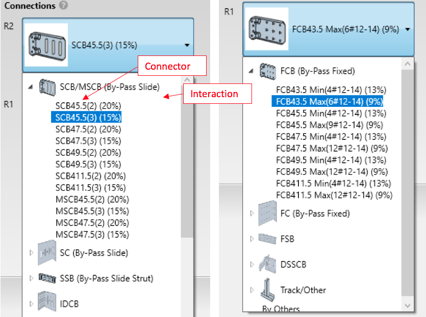
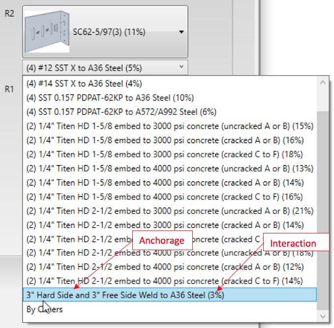
In addition to designing the connector, the software will also design the anchorage. The connector and the anchorage are selected separately, and interactions for each are shown so as to enable the engineer to make a well-informed connection choice (Reference Figures 1 and 2).

Figure 1. CFS Designer Software Connector Screen Shots (Left Side — Slip, Right Side — Fixed).

Figure 2. CFS Designer™ Software Anchorage Screen Shots.
There are many additional enhancements to CFS Designer v2.5.
Version 2.5 Enhancements
- A new stacked x-braced module has been added. The new module follows AISI S240 and S400 and allows up to eight stories. ASD or LRFD options available.
- A new stacked shearwall module has been added. The new module follows AISI S240 and S400 and allows up to eight stories. CFS Designer v2.5 allows LRFD input. Future versions will allow ASD.
- Connection design has been completely reworked in beam input and wall with opening module. Design is much more flexible. All Simpson Strong-Tie bypass connectors and all anchors in CFS catalog as well as base track, slotted track and slip track can be designed in CFS Designer. Rollers and pin supports have also been added to the beam input module.
- Wall with opening module general tab has been modified. Additional header load and additional stud axial load are now located under vertical loads and can be combined with wall self-weight. Option for excluding or including tributary self-weight has been added. Flexural bracing for jamb and stud has been separated, and bracing has been reorganized.
- Well over a dozen tool tips have been added to the software to help the Designer better understand what the software does and provide information that may be useful on particular subjects.
- Quick links to CAD drawings, connectors, code reports and technical topic articles have been added.
- Text space has been increased for models within the workspace, allowing longer names to be easier to read.
- Users can now organize the workspace either alphabetically or by the order of entry.
- There is now a standard name generator for custom shapes.
- Designers can now move any section of the wall with opening module members to the beam input.
- Output for beam input module has been slightly modified to make the section and connection information easier to read.
- Default Summary Report PDF file names have been modified to their model name.
A nine-minute video explaining all the enhancements included in CFS Designer v2.5is available on our website as well as on YouTube. Simpson Strong-Tie encourages you to learn about these enhancements and use them to increase your engineering productivity.
CFS Designer YouTube video:


