


With the introduction of the Simpson Strong-Tie Yield-Link® moment connection for steel construction, the engineering and software development teams at Simpson Strong-Tie created multiple design tools to support users in their specification of the Yield-Link technology. These tools range from a connection modeling guide and plugins for designers to detailing software add-ins for detailers. Below is a brief introduction to these tools for the different trades.
Engineers/Architects:
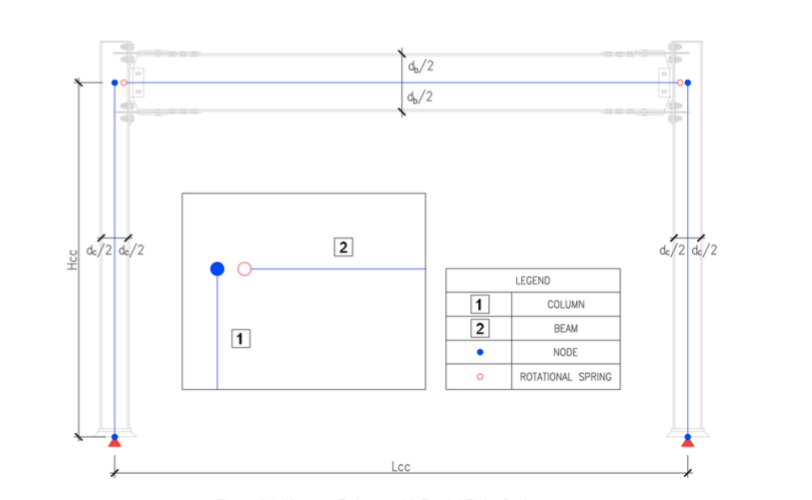
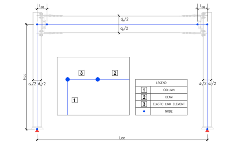
The Yield-Link® Connection Modeling Guide covers the different modeling techniques for the Yield-Link connection for engineering analysis and design software. It has step-by-step directions for incorporating the Yield-Link connection into different software so the stiffness of the Yield-Link connection can be captured correctly for drift and strength check. It offers users tips on where to extract the moment for calculating the Yield-Link forces and a preliminary chart for the initial Yield-Link design based on the connection moment demand load. (See Figures 1 and 2.)

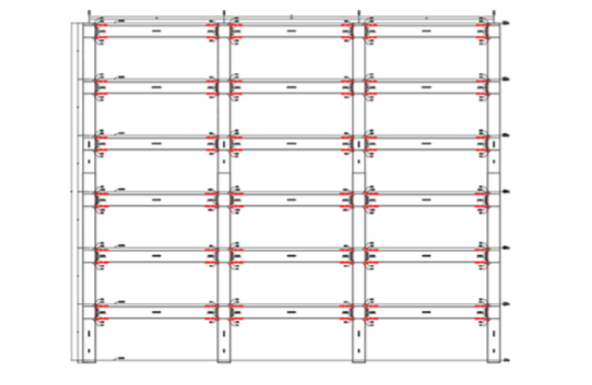
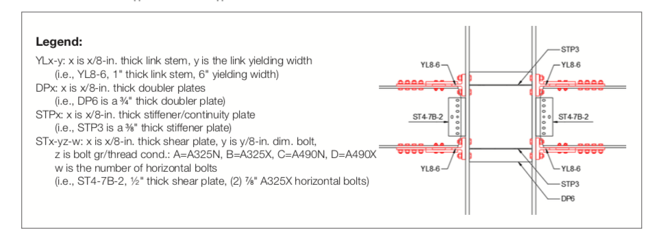
The Yield-Link® Connection Design Tool in Excel is a companion to the Yield-Link Connection Modeling Guide. The tool is written in Microsoft Excel with easy-to-follow step-by-step buttons that aid designers in a moment frame design using the Yield-Link connection (Figure 3). This tool has the ability to perform initial drift check, Yield-Link size check, Yield-Link connection check, shear plate check, and member check for the beams and columns. This design tool can also export the frame model to RISA-3D (Figure 4) for users to perform their final drift and member design checks. When the moment frame and Yield-Link connection designs are done, the Yield-Link Connection Design tool can output a .DXF file with frame elevation and all the relevant welding and bolting design information (Figure 5) for designers to incorporate into their design documents. The Yield-Link Connection Design Tool in Excel can be used with RAM, STAAD or any other structural software that has the ability to model a PR connection.


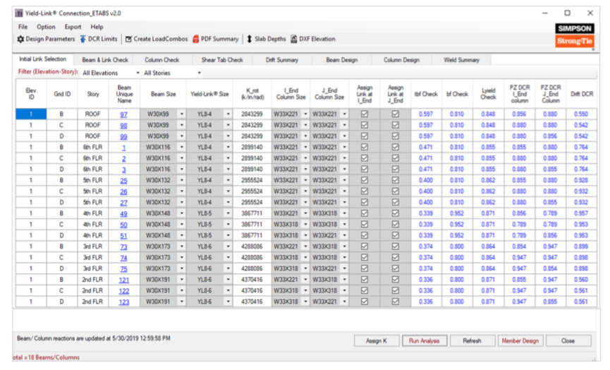
The Yield-Link® Connection Plugin for ETABS/SAP2000 is a software add-in for the well-known Computer and Structures, Inc. state-of-the-art analysis and design software applications. The Yield-Link plugin will automatically assign rotational springs to the ends of each beam when the user selects the beam size and link size from a drop-down menu (Figure 6). After all the initial checks, the user can run the frame analysis, and the plugin will automatically calculate the beam and Yield-Link check, column check, shear tab check and show a drift summary for wind and seismic loads. PDF output for detailed calculations can be requested for each beam or Yield-Link connection just by right-clicking the member name. After the frame designs are done, the user can export all the frame elevations (Figure 7) and welding/bolting details (Figure 8) in .DXF format for the designer to use in their design document.
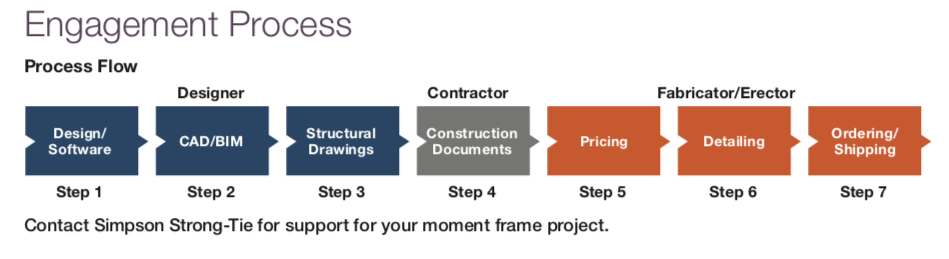
The Yield-Link® Connection Design Guide is a document summarizing the features and benefits of the Yield-Link connection. It documents the Yield-Link analysis and design assumptions as well as the entire Yield-Link product offering. The document also highlights the typical engagement process flow (Figure 9) for users who aren’t familiar with Yield-Link connection design and specification.
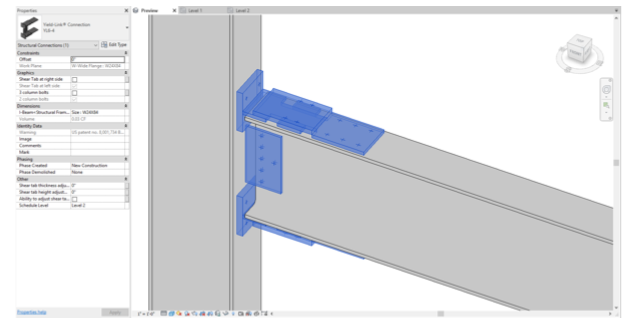
To complete the CAD/BIM details for the Yield-Link connection, Simpson Strong-Tie offers Yield-Link Connection Revit Families (Figure 10) for designers to use in their Revit architectural or structural models. The Revit families are developed to facilitate coordination between the different trades. The Yield-Link connection Revit families can be imported into a typical project and added to the beam-to-column connections. Once the Yield-Link connections are located on the frames, the user can export a schedule to summarize all the Yield-Link sizes and quantities used for the project. In addition to the Revit families, Simpson Strong-Tie has also generated a Yield-Link Connection Installation detail sheet in Revit format (Figure 11); this will allow the designer to have all the details in Revit without having to import and manipulate the CAD file.

For designers who are still working with AutoCAD on their connection details, we offer the Yield-Link Connection Installation detail sheet in CAD format. The detail sheet covers all the typical connection installation requirements as well as steel deck support details around the Yield-Link connection, and other miscellaneous installation situations.
For the project specifications, Simpson Strong-Tie has a Yield-Link® Connection Master Specification document available in the Microsoft Word format.
Currently we are in discussions with other Structural software companies to incorporate the Yield-Link connection in their software. We expect these additional tools to be available in 2020. Reach out to Simpson Strong-Tie if your office uses a particular design tool.
Fabricator/Detailers:
Once the Yield-Link® connections are specified on the project plan and specification documents using our design tools, the fabricator and steel detailer can incorporate the Yield-Link connection into their workflow with steel detailing tools we have available. The first of these tools is the Yield-Link Connection Tekla custom component.
Similar to other Tekla custom components, the Yield-Link connection custom component (Figure 12) is easy to use. It requires minimal input from the user to locate the correct holes on the beam/column and shear plate connections. Options for shear plate, continuity plate, and doubler plate are also available so the detailer can match the engineer’s requirement as noted on the construction documents. A case study on using our Yield-Link Connection Tekla custom component can be found here:

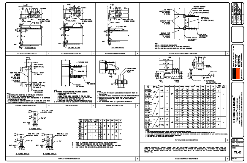
For those who are not working with Tekla, we offer the Yield-Link connection detailing sheet in CAD format (Figure 13). This sheet contains all the geometries on the Yield-Links so the detailer can locate the correct bolt-hole size and spacing on the beam and column components where they connect to the Yield-Link.
Simpson Strong Tie is currently working on a Yield-Link connection custom component for SDS/2 (Figure 14). Version 1.0 is expected by Q2 of 2020.

As shown from the tools presented above, Simpson Strong-Tie has streamlined the Yield-Link® connection integration for steel moment frame projects by giving users full control from documentation to production. You can explore these tools at strongtie.com/products/go/lateral-systems/yield-link-special-moment-frame-software-tools.
If you have any question, comments, or suggestions concerning our Yield-Link tools, please contact us at yieldlink@strongtie.com.
