In this post, we follow up on our October webinar, New Design Methods to Enclose Buildings Faster, by answering some of the interesting questions raised by attendees.
During the webinar, we discussed new design methods and solutions for curtain-wall and cladding connections and how they can maximize efficiency and resiliency throughout the construction process. In case you could not join our discussion, you can watch the on-demand webinar and earn PDH and CEU credits here.
As with previous webinars, we ended with a Q&A session for the attendees. Our Business Development Manager, Tim Ellis, and the founder of JEI Structural Engineering, Stewart Jeske, answered as many questions as they could in the time allowed. Now we are back to recap some of the commonly asked questions and their answers. If you’d like to see the full list click here. Some of the answers below are referenced in this list.
Join us for Part 2 of this webinar series for a more in-depth look into the engineering and design of the Edge-Tie™ System on November 9th, 2022.
Pricing/Supply
1. What is the pricing for the Edge-Tie™ system?
The Edge-Tie channel is $59/ft. sold directly to the steel fabricator and installed at the fabrication shop. T-bolt assemblies are sold to the façade installer.
2. Given the structural steel supply chain issues, what is the lead time availability of the extruded Edge-Tie system?
We have product stocked at our Simpson Strong-Tie facility. We are expected to keep an inventory of stock, so we do not have to make product specifically for each order.
3. If everyone uses this system, will there be supply shortages of this specialty pour stop?
IF everyone used this product, then, yes, we would have supply issues. However, we expect that the supply will ramp up as we educate and get repeat customers. We have product stocked at our Simpson Strong-Tie facility. We expect to keep an inventory of stock so we do not have to make product specifically for each order.
4. Since this new type of edge anchor is proprietary to Simpson Strong-Tie, it could be problematic when specifying on public bid projects that require a “3 or equal” type of specification. Are there other comparable systems on the market that we can specify, as well?
We are developing a new system for edge plate. We will be competing against traditional edge plates, and, therefore, a traditional alternative could be listed for public bid projects.
5. Do you have resources in Canada (e.g., near Toronto and Vancouver)?
Yes, we have facilities in Pitt Meadows and Brampton.
6. Who makes the product?
The Edge-Tie is a Simpson Strong-Tie product that is inventoried and tested at Simpson Strong-Tie facilities. Simpson has made an agreement with a vendor in the US to extrude the shape for us.
7. Is Simpson the only supplier for this Edge-Tie channel?
Simpson Strong-Tie is the only supplier of Edge-Tie. We stock this product at a Simpson facility and can ship anywhere in the US and Canada.
Testing
8. Was the bolt-and-channel assembly tested by a third party to provide load capacities for the design engineer? The assembly could see tension, shear, and bending loads due to eccentric vertical loading from the façade.
The bolt-and-channel assembly was tested in a Simpson Strong-Tie Certified Testing Laboratory and witnessed by a third party. Simpson is holding a second webinar that look at the engineering and design in more depth.
9. Does this slab closure system have a current ICC or IAPMO report?
We are currently working with ICC-ES on a code report.
10. Is it ASTM A36 or A992?
The Edge-Tie channel is made from ASTM A572 (Fy min = 60 ksi).
11. What ASTM code governs this system?
The Edge-Tie channel is made from ASTM A572 (Fy min = 60 ksi). The bolt is made from A449. There are currently no ASTM testing codes that cover similar slotted channel-and-bolt systems. However, there is an ICC Acceptance Criteria (AC541) that was developed for testing this system.
12. Does this system have ESR on them for the safety railing/cladding connection system?
The bolt-and-channel assembly were tested in a Simpson Strong-Tie Certified Testing Laboratory and witnessed by a third party. Simpson is holding a second webinar that will look at the engineering and design in more depth.
13. What is the expansion of AIA?
American Institute of Architects.
Safety Railing
14. Do you have to abandon the clips used to attach the safety railing system once you put the curtain wall on? It doesn’t seem possible to access the clips after the curtain wall is installed.
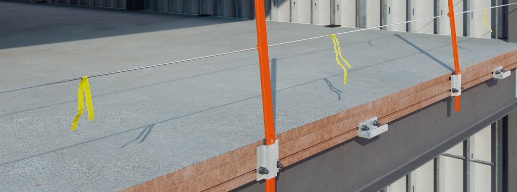
The guardrail post can be removed by simply lifting it out of the bracket. The guardrail bracket can typically be removed unless access is restricted for removal. The guardrail bracket can remain in place if there is inadequate access for removal.
15. Does the safety system work for code guardrail load prior to concrete placement?
Yes, the guard posts can be installed in the laydown area before the beams are flown into place so that all one has to do is straighten the cable once it is put into place and bolted in. It has been tested without any concrete.
16. Does the handrail meet OSHA requirements for 200 lb. at top of rail?
Yes, the guard rail post has been tested for the 200 lb. load required by OSHA.
Welding
17. Does this channel need to be welded at the front and back or only at the back?
It’s the same as the traditional bent plate pour stop attached to the top of a steel beam: Use stitch welds at both the top and the bottom. Refer to the Installation Details sheet.
18. If there is no welding, how does the extrusion connect to the steel structure?
There is no field welding with this product. The extrusion is stitch-welded to the structure. The fabricator will stitch weld this either onto the steel beam or to the outrigger.
19. How do you connect the steel extrusion to the L4x4 angle? Welded?
It would be welded at the steel fabricator. The detail would be very similar to outrigger details supporting an extended bent plate pour stop.
20. Do you also have to weld the whole channel to the steel beam?
21. Does the Edge-Tie system still require a welded stud or rebar embedded into the concrete on the metal deck to resolve the moment due to dead load on the system?
Not necessarily. Design calculations would need to confirm whether additional rebar or studs into the slab would be required. Several completed projects have not needed additional rebar or studs. An Excel design tool is available from Simpson Strong-Tie. Comparative analysis between the Edge-Tie and traditional bent plate pour stops reveals much less load is applied to the reinforcing/studs into the slab if required.
22. Is adjustability allowed for when the Edge-Tie system is welded directly to the steel beam in the shop?
No. But this is the same as a bent plate pour stop typically welded to the edge of a beam in the shop or in the field. Adjustments are typical for the cladding connection design to accommodate construction tolerance. In addition, a slotted bolted connection detail to the top flange of the beam is a possibility with the system; it would just need to be designed for load transfer. Refer to Simpson Strong-Tie’s detail sheet for the Edge-Tie system and answer 53.
23. Does the Edge-Tie system need to be continuously welded or can they be stitch-welded to the supporting beam (near side and far side)?
24. Who is responsible for the welding design to the top flange of the beam?
Typically, the Structural Engineer of Record (EOR) is responsible for the edge of slab detail and the design of the connections to the beam. It’s the same as the traditional bent plate pour stop: Usually, the weld is indicated in the edge of slab detail in the EOR’s construction plans. Simpson Strong-Tie is holding a second webinar that will look at design aids and example details in greater depth.
Miscellaneous Questions
25. Do you think modular building types are conducive for adaptive reuse?
Yes, if adaptive reuse is considered when designing modular-type construction. The fact that building components are built offsite and bolted together makes them easier to adapt for reuse if some consideration is given to that possible need during the construction phase. The Edge-Tie system will be easier to replace and reuse than a fixed or welded connection design in future renovations of façade systems.
26. This is a very specific solution for a glass curtain wall condition. How does the Edge-Tie product work with typical bypass metal stud CFS framing connections?
It can be used in the same manner as a bypass system, but with the added benefit of adjustability and installation speed. The Edge-Tie is also a great system for panelizing due to its adjustability. Refer to Simpson’s detail sheet for the Edge-Tie system.
27. Can you please provide more information on how the steel can be extruded in such a shape?
The production process is proprietary.
28. Can this be adapted for hollow core plank and CMU-bearing wall structural systems?
It’s possible as long as we can see a load path and design for the transfer of cladding loads to the structural elements.
29. How flexible is this system to adjust with longer cantilevered edges of the deck? For example, edges of the deck more than 1′ from the edge of the beam?
Very flexible for outrigger design to support. This is the same as the traditional bent plate pour stop: When the deck edges are 12″ or more from the beam edge, it’s typical to support the bent plate pour stop with outriggers from the beam. Please reference the Edge-Tie Standard Detail sheet.
30. What type of support do you need with a cambered beam?
Cambering of the Edge-Tie channel is done prior to welding to the steel beam in the steel fabrication shop. Please reference the Edge Tie Standard Detail sheet for limits on cambering.
31. Do these cast steel pour stops come in varied sizes? Or one standard size?
One standard size for now. A 1/4 steel plate is stitch-welded to the top of the channel at the steel fabricator for larger slab depths.
32. Do you have different section sizes for lightweight walls and larger for masonry, stone, or precast, or is it one size for all?
One standard size for now. The capacities are adequate for applications with higher load demands. Reference the upcoming Part 2 webinar.
33. Stone, masonry, and precast walls could demand larger loads for both in-plane and out-of-plane seismic lo Has this been addressed?
34. How does the connection work for in-plane seismic? Is the channel serrated or does the T-bolt create an indentation into the channel when tensioned?
ICC testing for slip-critical load testing will be available soon. The T-bolt head is serrated and is pretensioned in seismic applications. Simpson is holding a second webinar that will look at the engineering and design in greater depth.
35. Are these rated for seismic loads in the longitudinal axis of the channel?
36. What bolt sizes are accommodated in the Edge-Tie system?
The Edge-Tie T-bolt is 3/4″ in diameter and ranges in length from 1 1/2″ to 3″. Additional sizes may be added in the future.
37. Are there any torque requirements for the various bolting required?
Edge-Tie T-bolts shall be installed on the Edge-Tie channel as pretensioned for seismic applications (Seismic design categories C, D, E & F). Bolts can be pretensioned by washer indicating devices, turn-of-nut method, or calibrated wrench method. See specification for structural joints using high-strength bolts (latest edition) for requirements of these pretensioning methods.
38. Are bolts treated with Loctite or lock washers?
No.
39. How do you keep the nuts from loosening?
Bolts are snug tight or pretensioned. Refer to RCSC for requirements.
40. Is the inside of the channel roughened to allow it to be a slip-critical connection?
41. How does the contractor get the nut/washer inside the channel of the extruded shape, mid-piece? The only way is to feed it in via the open end. How does this work for a 120′-wide building where multiple nuts/washers will be used and likely “missed”?
42. Is it hot extruded? Simpson website indicates 60+ ksi
Yes, it is hot extruded.
43. It looks like the extruded profile is thicker than the 1/4″ bent plate. That would not be a fair comparison. Also, what about the wind zone where the forces are not as high as the corners: Can you install an extruded profile that is not as strong as the corner one? Can you mix the two systems, bent plate at the field zones and use the extrusion at the corners?
Mixing of systems on a building could happen. However, data shows cost savings and construction schedule savings for the Edge-Tie system over traditional bent plate pour stop applications. Mixing two systems may also create unforeseen difficulties at transition points between zones that would need appropriate engineering.
44. What will Von Mises be on the groove for a 4,150 lb. wind?
The channel has been tested for larger loads. Simpson is holding a second webinar that will look at the engineering and design in greater depth.
45. Can you please address corrosion issues for Florida and Hawaii’s hot, salty, humid air?
The system is behind the moisture barrier in buildings and should be treated the same as the traditional bent plate pour stop systems used with steel building framing.
46. What is the material used? Is this aluminum extruding or steel?
The Edge-Tie system is made of extruded high-strength steel A572.
47. How would vertical adjustments be handled? Masonry cladding?
Vertical adjustments are typically handled in the cladding connections/support design. This is no different than typical connections to the bent plate pour stops in practice currently. Please reference the Edge-Tie System standard details sheet.
48. Are there different connector types that lock into the channel, such as a connector that allows for vertical slip of the structure but resolves wind load only? Are there load tables for the connector types that are IBC/ICC rated and have allowable loads associated with them, considering both failure of the connector itself and failure of the channel flanges?
No, there is an additional item that needs to be installed by the curtain wall designer that allows the connection to slip in that plane. This would involve either a slot or a type of connection featuring a slotted hole. Those connections can be designed by the curtain wall designer just as if they were designing for a bent plate pour stop and its connection that had to be adjustable. We have done extensive testing both for wind and seismic loading. We are currently working with ICC on a code report.
49. Do the clips/anchors installed in the extruded pour-stop need to be inserted at the open end of the kerf and slid all the way down the length of the slab to get them in the proper locations?
The nature of the Edge-Tie T-bolt is that you put it in with the “T” section horizontal and then turn it 90 degrees to the right and the T-bolt has an interlocking profile to the back of the Edge-Tie channel that gets tighter as you tighten the nut. It can be placed anywhere along the channel and moved up 90 degrees and that locks the T-bolt in. There’s also a horizontal line indicator on the bolt that corresponds with the T-bolt to tell you when it is in the 90-degree locked position.
50. Are the clips steel or a different material concerned with potential galvanic action?
51. The online information does not include structural loading or actual dimensions. Is structural loading information available?
Please reference the upcoming webinar, which rolls out the design software that addresses structural loading and design calculations. ICC testing results will soon be available.
52. Can this system be used on a post-tensioned building?
Not this system.
53. Does this new system work on a curved building?
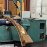
Yes, this system can be bent to specifications. The tightest specification met so far is a 25 ft. radius. The channel must be bent or cambered prior to installation onto the steel beam. Please see the Edge-Tie Details sheet.
54. How does it handle dead load deflection?
This should be the same way the traditional bent plate pour stop handles dead load deflection (or the anchor channel embed top of slab). Accommodation of vertical deflection of the structure is a design requirement for the cladding system and connection design to handle.
55. What is the dead load capacity loaded in a point on channel?
Extensive testing has been performed and ICC testing will be released soon. Please reference the upcoming webinar, which rolls out the design software that addresses structural loading and design calculations.
56. What is the yielding strength?
The design yield strength is 60 ksi.
57. What is the strength of the Edge-Tie as opposed to the regular steel angle due to the extrusion method?
58. How is the channel tied back into the slab?
59. Is the pour stop welded or can it be bolted to the channel or steel beam?
It’s possible to create a design that features bolting instead of welding to the steel beam. Refer to Edge-Tie system Standard Details sheet.
60. Is there an option to bolt the pour stop in the shop and eliminate all welds?
61. Does this bent plate provide rigidity to the parent beam member?
If so, it would be similar to the bent plate pour stop traditionally detailed in EOR drawings.
62. Can it be used without slab backing?
Yes, it does not require a concrete slab. Simpson is holding a second webinar that will go look at the engineering and design in greater depth.
63.Who provides and installs the new pour stop/anchor channel?
The Edge-Tie system is sold by Simpson Strong-Tie directly to the fabricator. See answer 65.
64. How do you connect the continuous extruded pour stop to the supporting beams or outriggers?
It’s welded in the steel fabrication shop and shipped to the jobsite, where it’s erected with the structure.
65. How does the extension tab work for adjusting the system to the required slab thickness?
A 1/4″ steel plate of varying height is stitch-welded to the top of the channel at the steel fabrication shop. See details sheet.
66. What is the detail for a pour concrete beam that is used in place of a metal frame?
The Edge-Tie system is for steel-framed structures. However, you could bolt the system to the concrete beam or attach it to an embed.


