

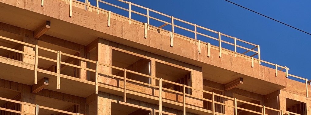
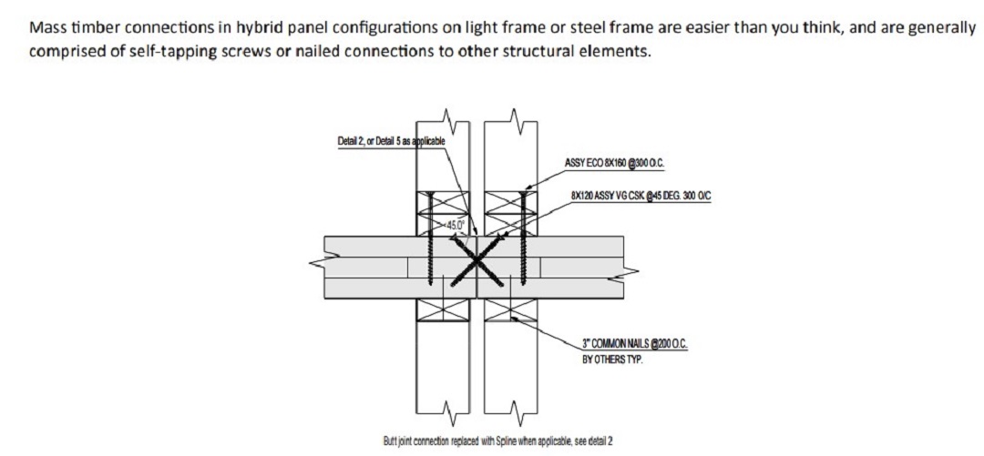
Mass timber floor panel systems for mid-rise light-frame wood construction are becoming more popular. Hybrid wood-framed systems have many advantages over conventional lumber floor systems such as 2×10/2×12 floor joist or I-joist systems.
Among the benefits of mass timber floor panel systems are the following:
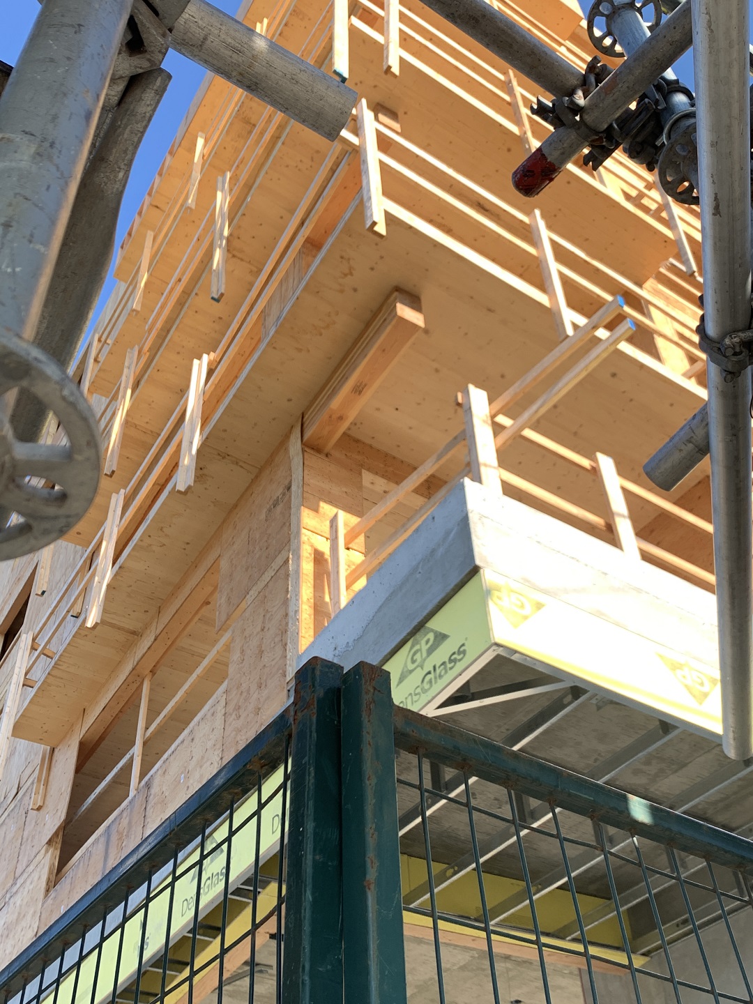
- Ease and speed of construction – Mass timber floor panels are manufactured offsite and delivered to the jobsite. This allows for quicker installation time per floor over the conventional site-built floor systems.
- Ease of sub-trade infrastructure work – Mechanical, plumbing and electrical subtrade work can be coordinated at the mass timber factory. So there’s less worry on the jobsite about framing around cut openings than with traditional floor systems.
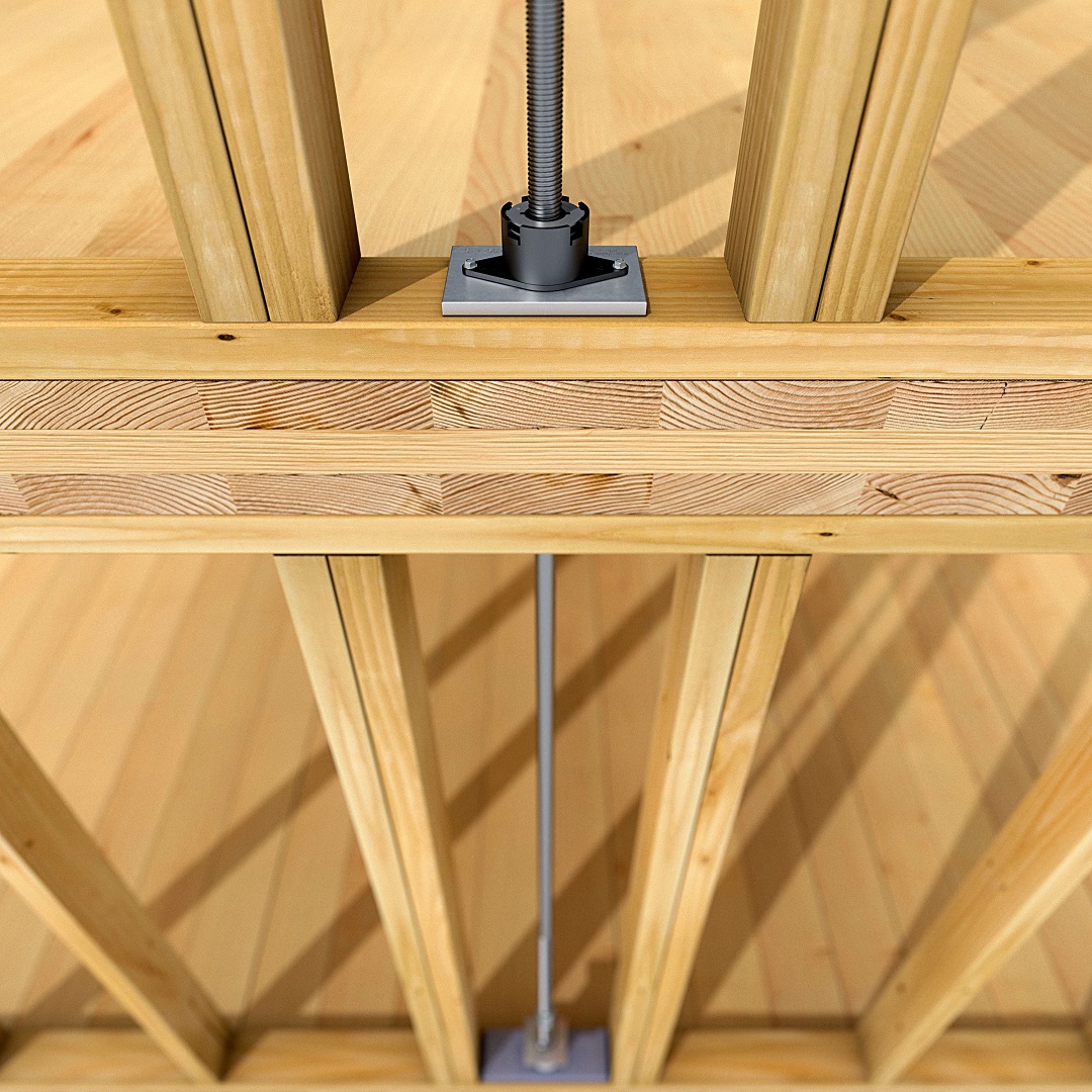
Anchor Tiedown System ATS

However, mass timber panel systems present their own challenges for designers. What are the concerns about mass timber floor panels in relation to lateral-force-resisting systems? Is the current practice of utilizing anchor tiedown systems (ATS) as shearwall holdowns through the adequate when paired with mass timber panels? The University of Northern British Columbia (UNBC) was engaged both to validate this hybrid wood-frame system and to provide guidance on detailing the ATS system in conjunction with mass timber panels.
A research report titled “Simpson ATS for CLT Floor Slab on Stick Frame Wood Stud Wall” by Asif Iqbal, Ph.D., P.E. (associate professor – UNBC School of Engineering) and Peter Whitehead (UNBC graduate student) provides the following summary.
Research Report Background
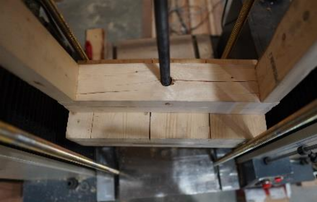
The purpose of the performed tests was to grasp an understanding of the limits of anchoring cross-laminated timber (CLT) using the Simpson RTUD/ATUD take-up device systems. This was done by creating a light wood-framed structure to test in compression using these Simpson connectors and various framing scenarios.
The constant parameters through all tests were 16” on-center studs, 2×4 framing, double top plates, and a 23.6” stud length (600 mm).
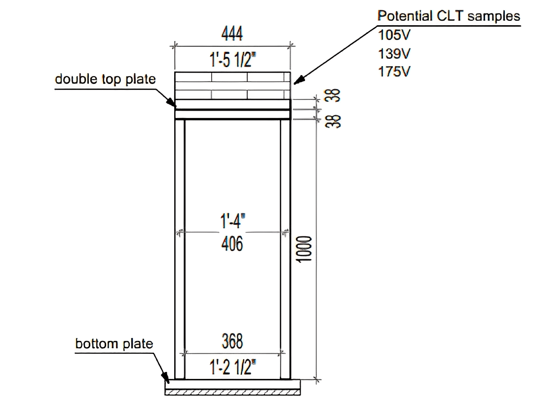
Variables in testing were threaded rod diameter (⅝” or ¾”), size and orientation of CLT, number of studs on each side, type of connector used, and whether or not sheathing was included. Additionally, tests with ATUDs included a bottom plate to emulate the next level of framing.
Parameters Investigated
CLT Orientation
Two different sizes of CLT were used in testing – 105V and 139V. The reason only these two types were utilized has to do simply with what sizes are easiest to use in light wood-frame construction. Anything larger than this size in industry is used mostly in post and beam construction techniques. Size 105 panels have historically been the size used for these types of structures, although size 139 panels have also been used for higher-end buildings with larger spans.
Tests for these sizes were performed in the major strength span as well as in the minor strength span. The reason they were tested in both strength spans relates to the uncertainty about where an anchor might be installed. Different anchor locations will provide very different reactions in the panels, so it will be up to a designer to strategically place rod anchors in walls depending on the orientation to the floor span direction.
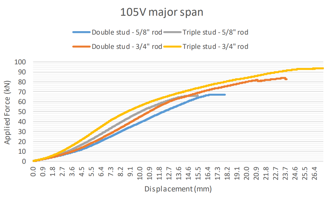
Number of Studs
For testing, only 600 mm long 2×4 studs were used. Testing was done using multiple studs on each side, but the outside studs were always 16” on center. By adding studs, two variables in strength were altered. When studs were added, the surface area for stud bearing was increased, which led to a higher resistance to wood fiber crushing, and the amount of space for vulnerable materials to bend was decreased, thereby minimizing bending failure.
Threaded Rod Diameter
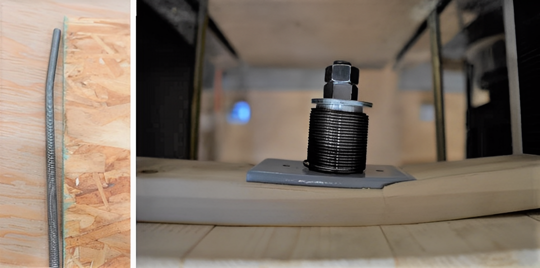
Two different ATS threaded rod sizes were used for these tests – ⅝” and ¾”. The reason both these popular rod sizes were tested was to identify how they affected the results. While connectors varied in size depending on the rod diameter, the steel mounting plates bearing on the CLT had the same dimensions in all tests.
Types of Connectors
Both RTUD and ATUD systems were tested. The RTUD was tested in greater depth, but RTUDs have the potential to be installed directly on the CLT, whereas ATUDs are intended to be installed mid-span to accommodate wood shrinkage and rod stretching. This means the ATUDs were installed on a bottom plate rather than the on the CLT, and in all the tests damage to CLT was only correlated to direct compression resistance from the steel plate installed with the RTUD.
Sheathing
Four tests were done using either single or double-sided OSB sheathing. In all cases, the sheathing made the framing system much stiffer, although it also forced failure into the bottom plate used with the ATUD system, crushing wood fiber perpendicular to grain at around 50 kN.
Observations and Types of Failure:
- Fiber crushing – Wood was crushed perpendicular to grain.
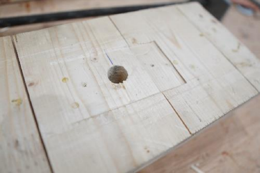
2. Flexural cracking – All bending failures occurred in the bottom top plate of the framing configuration.
3. Rod stretching and rod bending – Typical rod failure occurred after the wood crushing failure. With the ATUD shrinkage compensating take-up device attached to the steel rod, localized bending in the rod was observed. Usually, the steel bearing plate would crush into the wood fiber, kinking the rod. With the RTUD shrinkage compensating take-up device, there was minimal localized kinking in the steel rod.
Conclusions and Recommendations:
- CLT panels with Simpson Strong-Tie is a good solution as a floor system for buildings and a viable alternative to traditional floor systems with lumber or I-joists.
- Based on the experimental results, triple studs on either side of the ATS rod system is recommended to reduce the inelastic deformation due to wood crushing under load. The inherent differences between the CLT major and minor spans have to be accommodated carefully through allowing differential deformations while maintaining displacement compatibility and load sharing within the overall arrangement. Additional research is suggested to provide a more in-depth rationale and analysis methodology.
- The CLT floor system is observed to have the capacity to resist the loading applied with the test arrangement and stud spacing.


Want to learn more about Mass Timber and CLT? We have a blog for that.
What is Mass Timber Construction?
