

This is the last of a three-part series covering common questions we receive in our engineering department. Part 1 consisted of frequently asked questions related to our anchor products (view Part 1 here), while part 2 covered connector products (view Part 2 here). These are questions that come directly into our call center, along with questions submitted through the website, our engineering email queues, and our sales team.
In part 3 of this series, I will be covering fastener questions related to use with our connectors, for both wood and cold-formed steel (CFS) applications. Most of the answers to these questions can be found in our connector and fastener catalogs.
Let’s jump right in with the most common fastener question, which is:
“How long should a self-drilling screw be when connecting CFS connectors?”
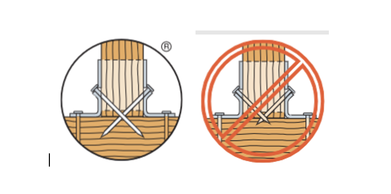
Per our specification, it is recommended that the screw be long enough to penetrate the steel and have three exposed threads onto the opposite side of the carrying member as is required per code. Remember that the diameter will also be determined by the gauge of the steel being attached to and the member being carried. On most load tables, the screw diameter required to achieve full load value is listed.
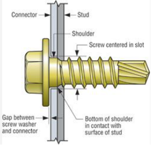
As seen in detail above, you would want to make sure that the screw is long enough for the self-drilling tip to penetrate the carrying member and visibly have three threads on the opposite end.
The second most common connector product question we receive is:
“Can I substitute a screw for a connector nail?”
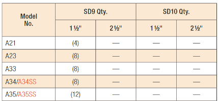
The answer to this depends on several factors. We have tested many connectors that fall under the list of Connectors Approved for Use with the Strong-Drive® SD Connector Screw found both in our connector catalog and on our website. When searching for this list, I would recommend first referencing the list available online as we are constantly testing and updating this information. The list will provide you with the quantity and size of screws required for the application.
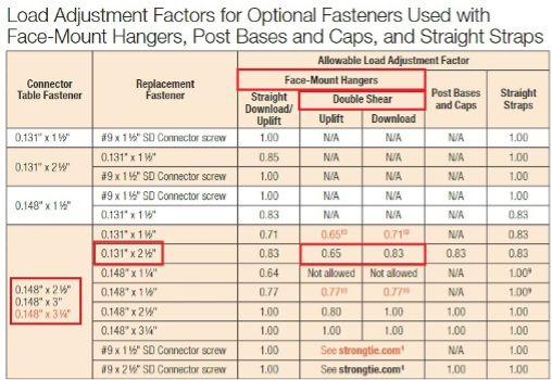
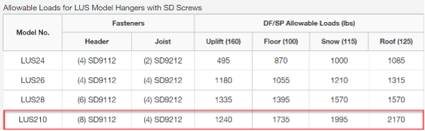
For model numbers not available on this list, you can reference our load adjustment factor table listed on p. 22 of C-C-2021 for optional fastener options for face-mount hangers, post bases and caps, and straight straps. This will provide you not only with replacement screw options, but with alternative nail options as well. Note that these options sometimes require a load reduction based on an adjustment factor provided in the table. Take LUS210 as an example. If you substitute the table-listed fastener of an 10d common (0.148″ diameter x 3″ long) with the 0.131″ diameter x 2.5” long nail, you need to apply a 0.65 adjustment factor to the allowable uplift load and 0.83 adjustment factor to the allowable download. Because of the double-shear penetration design of the hanger, the reduction in allowable uplift is greater due to the substation of a shorter nail.
On the other hand, if you were to replace the nail with a SD9212 (#9 x 2.5″) per our SD approved list, you will not only meet but exceed the published nail loads. Note that this will not always be the case, so we strongly urge you either to check our approved SD list or to reference the load adjustment factor table for any load reductions.
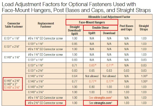
Please note that all hangers requiring double-shear nailing must use a minimum 2½”-long nails or 2½”-long SD screws. Shorter fasteners into the joist are not permitted.
The third-most common connector product question we receive is:
“Do you offer lag screws?”
When it comes to attachments of wood ledgers, or other wood members you are looking to connect, we do offer lag screw alternatives for wood-to-wood applications.
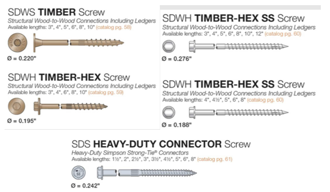
Our screw fasteners are a great load-rated alternative to lag screws because they require no predrilling, whereas lags need to be predrilled twice. The first time would be for the thread portion and the second for the upper shaft — all of which can be laborious and very time consuming, as it requires two different diameter drill bits. Simpson Strong-Tie has developed an engineering letter (L-F-LAGSUB23) with useful reference tables showing Simpson Strong-Tie screw options that meet or exceed the shear capacities of lag screws. The tables list minimum thread penetration, fastener spacing, and substitution callouts based on lag screw size and lumber species.
As an example, let’s assume you’re looking for a ¼” lag substitute for Douglas fir (DF) to attach a 4½” wood side plate. You will notice in the chart below that the SDWS22600DB can be considered as an option for your application.
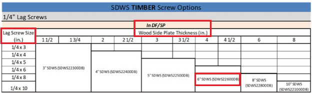
Most of these screws are available in a double-barrier (DBB) coating or Type 316 stainless steel for additional corrosion protection, and this letter can be used to justify your screw substitution.
The fourth and final common anchor question we receive is:
“Is predrilling required for your wood screws?”
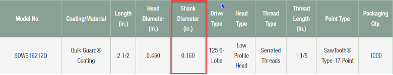
We typically do not recommend or require predrilling for any of our screws, as they’re designed to drive easily and reduce the risk of wood splitting. However, we do understand that you may have a condition where predrilling might be needed. A couple of these reasons could be retrofitting an old structure where you want to minimize the possibility of wood splitting, or make sure the screw goes in perfectly plumb. Per the National Design Standard (NDS), Section 12.1.5.3 (b), for specific gravity G< 0.6, the part of the lead hole receiving the shank shall be about 7/8 the diameter of the shank and that receiving the threaded portion shall have about 7/8 the diameter of the screw at the root of the thread. The specific gravity for lumber species can be found in the NDS or the General Notes section of our connector catalog. The shank diameter will usually be listed in the product information table within the model series homepage, as shown below. Note that it’s always 7/8 of the shank and not the thread diameter to make sure you still achieve full published load capacity.
Taking the SDWS16120 as an example, with a shank diameter of 0.160″, the predrilled hole (lead hole) cannot be any larger than 0.140″ (shank 0.160“ x .875 = lead hole 0.140“).
I do hope you have found this information helpful. If you have any questions, please do not hesitate to contact us through our technical support webpage or reach out to our engineering department directly for further assistance. The information in this blog is current as of today when I am writing it, but as a company that is constantly improving, always stay tuned for updates and never hesitate to call us for the latest information.
