In April’s post about the Omega Factor, one commenter asked of the 1.2 increase allowed by ASCE 12.4.3.3, “Why do they allow a stress increase for allowable combinations? Seems unconservative for steel now that they have essentially balanced the ASD capacity with LRFD.”
To be honest, I have never spent much time analyzing which design methodology was more or less conservative. If I was designing with wood I would use ASD, and if it was with concrete I would use LRFD. Steel was strictly ASD early on in my design career, but LRFD usage grew. The question about balance made me curious. Are the load combinations balanced?
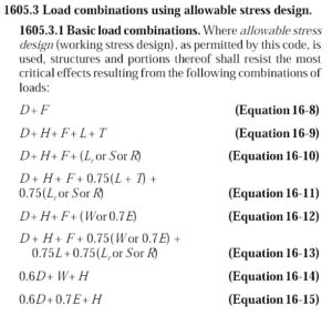
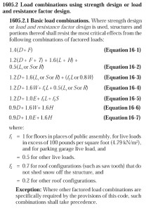
Of course, just comparing the load combinations would be meaningless. We know the LRFD combinations result in higher design forces. But those higher forces are compared to higher design strengths. So we need to normalize things.
The AISC Specification for Structural Steel Buildings, ANSI/AISC 360-10 is a unified standard where each limit state has a nominal strength, Rn. For LRFD you multiply by a resistance factor, ɸ, to obtain the design strength, ɸRn. Divide the nominal strength by a safety factor, Ω, to obtain the allowable strength, Rn/Ω, to use for ASD.
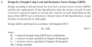
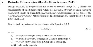
The values of ɸ and Ω in the AISC Specification are typically ɸ=0.9, Ω=1.67 for limit states such as flexure or shear, or ɸ=0.75, Ω=2.0 for net section rupture. In each case, however, the value of ɸΩ = 1.5, meaning the ratio of design strength to allowable strength is 1.5 for steel. This makes a comparison of the design methodologies for steel relatively simple.
The National Design Specification (NDS) for Wood Construction is somewhat similar, with Appendix N using format conversion factors, KF, to convert ASD capacities to nominal and then resistance factors to go from nominal to design strength. To account for allowable stress increases, the conversion uses ASD capacities at normal duration of load also applies a Time Effect Factor, λ, which varies by load combination.
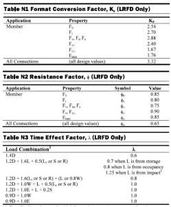
A similar comparison can be done for wood, where ɸKF = 2.16 (ignoring Fc-perp). But factoring in load duration and time effect factors, you get a ratio of design strength to allowable strength that varies from 1.35 to 1.73 depending on your load combination.
Huh?
Maybe an example with numbers for the wood will make that more clear. For an ASD wood capacity of 1000 lbs at a Cd = 1.00. The LRFD design strength will be,
ɸKF x (ASD capacity) x (time effect factor, λ)
For a dead load plus occupancy live load application, λ = 0.8 (per NDS Table N3)
ASD strength = 1000 lbs (Cd = 1.00)
LRFD design strength = 2.16 x 1000 lbs x 0.8 = 1728 lbs
So the ratio of design strength to allowable strength is 1.73.
For a wind or earthquake load combination, λ = 1.0 (per NDS Table N3) but we have a load duration factor, Cd of 1.6 on allowable load. So,
ASD strength = 1.6 x 1000 lbs = 1600 lbs
LRFD design strength = 2.16 x 1000 lbs x 1.0 = 2160
The ratio of design strength to allowable strength in this case is 2160/1600 = 1.35.
To see how a comparison of the load combinations works with these ratios, I’ll pick a simple D+L load case where D=L = 1000. The load combinations would be,
(LRFD EQ 16-2) 1.2D + 1.6L = 1.2×1000 + 1.6×1000 = 2800
(ASD EQ 16-9) D + L = 1000 + 1000 = 2000
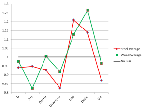
The ratio of design strength to allowable strength is 1.5 for steel and 1.73 for wood. If we compare steel first, we have (2800/1.5) / 2000 = 0.93. For wood, we have (2800/1.73) / 2000 = 0.81. If the number is less than 1.00 then there is a bias toward LRFD and LRFD is less conservative. A number greater than 1.00 is a bias toward ASD.
The chart below is the comparison of about 350 load cases with D, L, Lr and W/E loads varying from 0 to 2000.
For the cases with only gravity loads, LRFD combinations appear to give a more efficient design for most cases. Whether or not those efficiencies can be realized may depend on whether or not other limits such as deflection govern member sizes. When you add in short term wind or earthquake loading, the results are mixed and neither methodology has a clear advantage.
Do you choose between LRFD or ASD to get the most efficient design? Let us know by posting a comment.
– Paul
What are your thoughts? Visit the blog and leave a comment!





YOU ACT LIKE YOU KNOW WHAT LOADS ARE ON THE STRUCTURE. YOU ACT LIKE YOU KNOW WHAT FAILURE IS. YOU CAN ARGUE ALL. THE COST DIFFERANCE IS SMALL. WHEN SOMTHING FALLS NO ONE SAYS THE DESIGNER SHOULD HAVE USED 1.7 INSTEAD OF 1.6.
I would not claim to know the exact loads on a structure are. We do our best estimate based on judgement and mechanics. The load combinations help to maintain certain minimum safety factors to deal with the uncertainty in loading, tolerances, and variation in quality of materials.
I’ve always loved this quote about structural engineering since I first heard it in college.
“Structural engineering is the art of modelling materials we do not wholly understand into shapes we cannot precisely analyse so as to withstand forces we cannot properly assess in such a way that the public at large has no reason to suspect the extent of our ignorance.”
Structure Magazine did an article about it’s origins here: http://www.structuremag.org/article.aspx?articleid=829
Thank you for this amazing content!
I usually prefer LRFD as I believe it more accurately reflects that our uncertainty is higher for “live loads” than “dead loads”, so if you have high dead loads, your uncertainty and your “factor of safety” should be smaller, whereas if you are live load dominated your uncertainty is higher, so your factor of safety must also be higher. The real thing that is holding back timber LRFD in my opinion is best captured by “Wood Construction Connections 2013-2014”, C-2013 catelog, page 18, “General Instructions for the Designer”, Note n. The “Guideline” was incorporated into the 1996 NDS, discontinued, and now absent from the 2012 NDS. The fact it was discontinued so long ago makes it virtually impossible to find. Even Note n discouraging the “soft convension”, makes it very difficult to efficiently use the connectors we rely on to transfer loads with LRFD. Per Note n.: “When designing with LRFD, reference lateral resistances must be used. Contact Simpson Strong-Tie for reference lateral resistances of products listed in this catalog.” It would be really nice if an LRFD catalog were available, and would encourage the use of LRFD. As is, my tendancy is toward ASD just to be able to get compatibility with catalog cut sheets. Even things like ICC-ES ESR-1679 or ESR-3096 are ASD only.
The challenge of providing LRFD values for all of our connectors lies in the conversion of test limits, since there is not a recognized standard for it. We can do the calculations in LRFD, but it is not clear what Phi factor would be applicable to a tested ultimate and what deflection limit should be used for LRFD.
Some of the more recent Acceptance Criteria included a conversion which is published in our code reports. For concrete anchorage, ESR-2555 (Mudsill Anchors), ESR-2930 (STHD Holdowns), and ESR-2611 (SSTB/SB Anchor Bolts) allow the tabulated allowable loads to be multiplied by 1.4 and 1.6 to obtain LRFD loads for seismic and wind, respectively. AC155 for holdowns allows ASD loads to be multiplied by 1.4 to obtain LRFD values, and this is included in ER-143 (Bolted Holdowns), ESR-2330 (Screw Holdowns), ER-130 (Nailed Holdowns).
A 1.6 or 1.4 conversion factor is not too controversial for products that are predominantly used for wind or seismic loads. A conversion factor that works for general connectors might take a bit more work to develop consensus.
I am a fan of ASD. I can readily tell which load combination will control, I don’t have to re-do any calculations to determine deflections, etc… I even like ASD for concrete since generally I am concerned about making my concrete hold water. I can do it LRFD, but then have to go back and use service loads to make sure my cracking is acceptable.
The blog post lists load combinations from the 2009 IBC and provisions from AISC 360-10 and the NDS-12. Neither of these material standards apply to the provisions of the 2009 IBC but they do apply to the provisions of the 2012 IBC and 2015 IBC. Also, the load combinations in the 2009 IBC are compatible with the corresponding load combinations in ASCE 7-05 but not those in ASCE 7-10. There were several changes to the provisions of ASCE 7-05 and these changes were incorporated into the 2012 IBC so that the 2012 IBC load combinations are compatible with the ASCE 7-10 load combinations. This compatibility is maintained in the 2015 IBC.
I use ASD for wood and steel design since most floors are controlled by either deflection or vibrations. It doesn’t make sense to calculate all your loads using LRFD load factors and then convert them back to service loads to check dead and live load deflection and if the client wants a floor that feels solid you check vibrations for the floor system. Generally you need deeper or heaver beams and joists to satisfy the vibration criteria. Any discussion on which method ASD or LRFD provides the most economical structure is a moot point if your clients satisfaction with the finished product is your main concern.
If it is a spec building and the client doesn’t care about anything but the bottom line because he just wants to unload the building on someone else and take the money and run then the designer needs to decide whether the need to keep this client happy is more important than having to explain to the eventual owner why his floors are so bouncy.
can you explain more where the factor loadings has been derived. like the 1.2 for dead load and 1.6 for live load where they came from?
Informative comments – Apropos if you are requiring a a form , my kids discovered a fillable form here
http://goo.gl/6Mzz39As a young engineer who was thrown into the design world using both LRFD and ASD (I had no background with ASD before seeing the impact of starting to use LRFD method), this is a very helpful and easily understood comparison. I imagine working in ASD before LRFD implementation would have made the LRFD differences easier to understand, albeit likely a resisted change. But props to Simpson for making code topics like this easy-to-digest.