

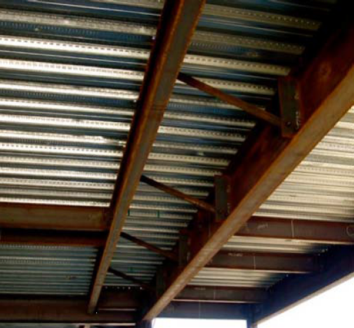
In a previous blog post on soft-story retrofits, I briefly discussed beam bracing requirements for moment frames. This week, I wanted to go into more detail on the subject because it’s important to understand that a typical steel moment frame requires lateral beam bracing to develop its full moment capacity. Figure 1 below shows two common methods of beam bracing. While on the surface determining beam bracing requirements may not appear complicated, there are several items that could prove it to be more challenging than you might think, especially when steel moment frames are used in light frame construction.
Figure 1: Steel Beam Bracing
Before going into beam bracing in steel moment frames, it is important to discuss the behavior of a simply supported beam under gravity load. Short beams (Lb < Lp)[3], might not require bracing to achieve the full plastic moment of the beam section. However, when a beam is long (Lb > Lr) and without bracing, the beam can twist or buckle out-of-plane. Figure 2 illustrates these two behaviors along with the case where the beam length is somewhere in between the two (e.g., Inelastic lateral torsional buckling). In addition, if beam sections are non-compact, flange local buckling (FLB) or web local buckling can occur prior to reaching the beams full plastic moment.
Figure 2: Nominal Flexural Strength vs. Unbraced Length

Under axial load, the beam can a) twist [Torsional Buckling], b) buckle out-of-plane [Flexural Buckling] or c) twist and buckle out-of-plane [Flexural-Torsional Buckling], see Figure 3 below. For W-section shapes, flexural-torsional buckling typically does not occur; this failure mode occurs most commonly in unsymmetrical shapes.
Figure 3: Beam Buckling Modes


Now knowing the possible failure modes of steel beams under flexural or axial loads, let’s see how our steel design codes address these concerns in a moment frame. In high seismic regions, design codes required compact sections to prevent beam flange or web buckling prior to the beam reaching its full plastic moment. To prevent torsional or flexural beam buckling, torsional or lateral bracing is required by code. AISC 360-10 Appendix 6 lists the strength and stiffness requirements for such bracing. Depending on how the beam is braced (relative or nodal), different strengths and stiffnesses are required to prevent flexural buckling. Similar requirements exist for torsional buckling. Please note the requirements for BOTH strength AND stiffness when designing for the beam bracing.
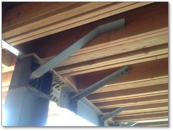
In structural steel buildings, use of bracing beam with full depth shear tab or diagonal kickers to the beam bottom flange along with concrete filled metal desk might be sufficient to meet the beam bracing strength and stiffness requirements. However, when it comes to bracing the steel moment frame beams in light frame construction, it’s difficult to satisfy these two requirements, especially the stiffness requirement. (Please see the beam bracing segment in our article, “Steel Moment Frame-History and Evolution”).
What happens if the provided beam bracing has insufficient strength or stiffness, or if it’s not provided at all? In traditional steel frames where the beam yields and is expected to form plastic hinge(s), the beam might buckle (either flexural or torsional) prior to the formation of plastic hinge(s), thus leading to a lower frame capacity. Figure 4 illustrates this phenomenon, where the reduction in moment capacity is due to premature buckling of the beam. Please note, for moderately and highly ductile members, in addition to the beam bracing between supports, bracing at the moment connection regions are required in AISC 341-10 where plastic hinges are expected to occur.
Figure 4: Nominal Flexural Strength vs. Beam Deflection

Now the trick question: What if there is a long beam span and the architectural requirements prevent the installation of beam bracing?
Typically, engineers have addressed this question by using moment frames where there is little or no beam yielding, such as ordinary moment frames (OMFs), and designing the beam for the clear span between the support columns. While eliminating beam bracing, this solution penalizes the foundation, diaphragm, and potentially other lateral resisting elements designed due to the low R-value of an OMF.
Fortunately, there is a solution that prevents designers from being penalized! With the introduction of the Simpson Strong-Tie® Strong Frame® Special Moment Frame (SMF) where the Yield-LinksTM are the elements designed to be the fuse (plastic hinge), no beam bracing is required. There is no beam inelastic lateral torsional buckling since the beam remains essentially elastic because yielding is taking place at the Yield-Links and not in the beam itself. There is no beam elastic torsional buckling because the beam is designed to span between the supports for the maximum load the Yield-Link system can deliver.
Figure 5 below is a plot from our finite element analysis showing the equivalent strain in the moment connection. As can be seen from the figure, all the yielding is concentrated (indicated by the green color) in the Yield-Links. This elastic beam behavior is supported by our testing as shown in Figure 6. Strain gages placed on the beam bottom flange near the moment connection clearly show the elastic behavior in the beam. Please note the symmetry of the readings on strain gages placed on each side of the beam. The overlapping of the red and blue lines indicating no torsional or flexural buckling occurred in the beam during testing, even at a frame drift level of 6%.
Go here to learn more about the SMF.
Figure 5: Plastic Strain (PEEQ) Plot of Simpson Strong-TIe Strong Frame Special Moment Frame at 0.04 radians
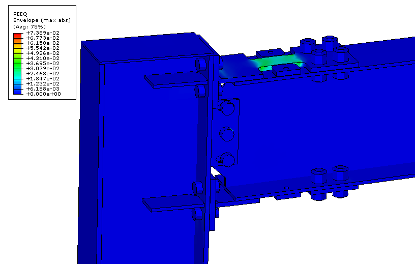
Figure 6: Measured Strain from Testing vs. Yield Strain at Beam Bottom Flange

References
[1] Photo credit: NEHRP Seismic Design Technical Brief No. 2: Seismic Design of Steel Special Moment Frames: A Guide for Practicing Engineers, NIST GCR 09-917-3, June 2009.
[2] Photo credit: Bobby Madrid, Simpson Strong-Tie.
[3] For definition of Lb, Lr and Lp, please refer to AISC 360-10.
What are your thoughts? Please let us know by posting a comment.
– Paul
What are your thoughts? Visit the blog and leave a comment!

Nice job! Very clever way to introduce a reduced beam section without requiring beam coping. Thanks for providing another tool in our engineering toolbox.