

Two weeks ago, I had the chance to present to the Young Members Group of the Structural Engineering Association of Metro Washington on the topic of Multi-Story Light-Frame Shear Wall Design. With all of the large firms in the D.C. area, it wasn’t a big surprise to find out that only about one-third of the group had experience with light-frame shear wall design.
However, while researching civil/structural engineering programs in the Midwest and Northeast last week (for our Structural Engineering/Architecture Student Scholarship program), I was disappointed to find that only about a quarter of the top engineering programs offer a wood design course. So I thought it might be helpful to post a wood shear wall design example this week.
The example is fairly basic but includes an individual full-height and perforated shear wall analysis for the same condition. The design is based on wind loading and SPF framing, both common in the Midwest/Northeast, and is based on the provisions and terms listed in the 2008 Special Design Provisions for Wind and Seismic (SDPWS), available for free download here, along with the recently posted 2015 version.
Multi-Story Shear Wall Example: Wind Loads with SPF Framing
Given: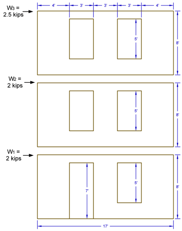
- 2012 IBC & 2008 SDPWS
- 3-Story Wood Framed Shear Wall Line
- ASD Diaphragm Shear Forces from Wind as Shown
- Wall and Opening Dimensions as Shown
Solution:
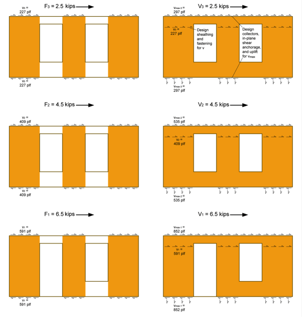
- Determine total shear force in each shear wall line.
- Determine the Induced Unit Shear Force, v, for use with both shear wall types and the Maximum Induced Unit Shear Force, vmax, for the perforated shear wall collectors, shear transfer, and uniform uplift. Note the following:
- vmax requires the determination of the Shear Capacity Adjustment Factor, CO, for the perforated shear wall.
- The SDPWS provides two methods for determining CO, a tabulated value or a calculated value. This example uses the more precise calculated value.
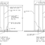
- The perforated method requires the collectors be designed for vmax and the bottom plate to be anchored for a uniform uplift equal to vmax (as illustrated in the following figure).

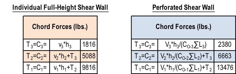
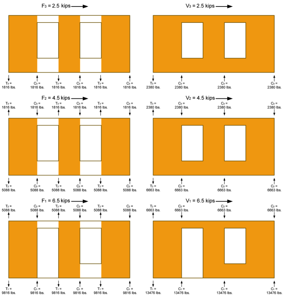
 3. Determine the Tension, T, and Compression, C, forces in the chords (assume no contribution from dead load for this example). Note the following:
- Reverse wind loading will require a mirror image of the T & C forces shown in the following figure.
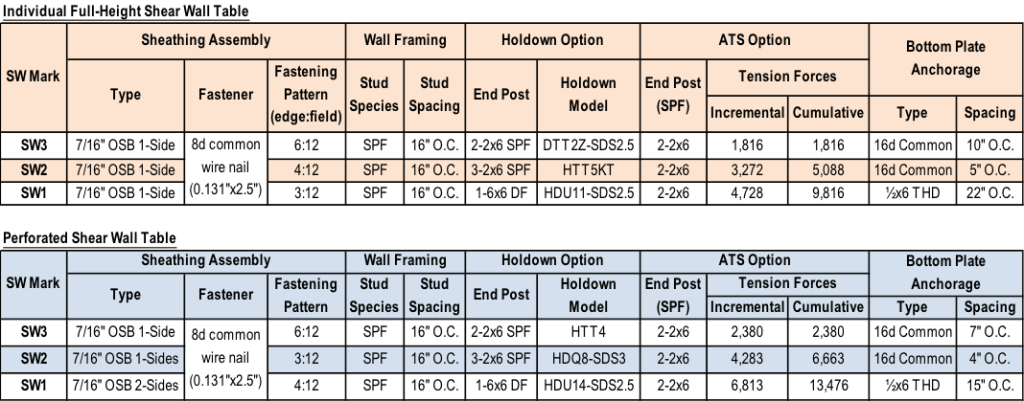
- The tension forces, T, shown in the example reflect the cumulative tension forces as they are transferred down from post-to-post, as is typical with traditional holdowns. For continuous rod systems like ATS, the incremental tension forces (resulting from the unit shear, vor vmax, at that level only) must also be determined as shown in the shear wall specification table at the end of this example.

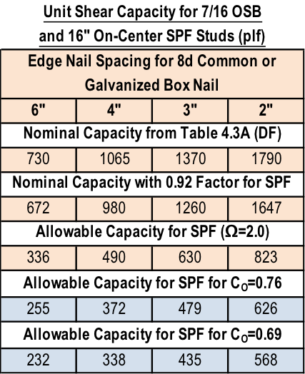
 4. Determine sheathing material and fastening pattern based on v calculated in Step 2. The table below is based on 7/16″ wood structural panel sheathing values in SDPWS Table 4.3A.
- Individual Full-Height Shear Wall:
i. v3=227 plf: Use 7/16 OSB with a 6:12 nailing pattern which has an allowable load of 336 plf
ii. v2=409 plf: Use 7/16 OSB with a 4:12 nailing pattern which has an allowable load of 490 plf
iii. v1=591 plf: Use 7/16 OSB with a 3:12 nailing pattern which has an allowable load of 630 plf
B. Perforated Shear Wall (apply CO factor to allowable shear capacity):
i. v3=227 plf: Use 7/16 OSB with a 6:12 nailing pattern which has an allowable load of 255 plf
ii. v2=409 plf: Use 7/16 OSB with a 3:12 nailing pattern which has an allowable load of 479 plf
iii. v1=591 plf: Use 7/16 OSB on both sides of the wall with a 4:12 nailing pattern which has an allowable load of 338*2=676 plf
5. Size the posts for compression. Simpson provides some useful tables in the back of the connector catalog with allowable tension and compression loads for a variety of sizes, heights, and species of posts.
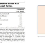
6. Select holdowns for the tensions loads and verify post sizes are sufficient. For higher aspect ratio shear walls, the post size and holdown type may significantly reduce the moment arm between center of tension and center of compression, resulting in higher tension and compression forces.
The tables below show the shear wall specification for the walls in the example in a typical format. Note that they do not include some detailing that is required for items such as the uniform uplift force on the bottom plate of all perforated shear walls, or the perforated shear walls with OSB sheathing on both sides.
There are different ways to address the loads, so let us know if you would do anything differently in your designs.


Has Simpson ever done any load testing on actual hold down forces vs. theoretical when the upper level has enough wall length to eliminate hold downs (straps), but the lower level has a shear walls that do require hold downs? I wonder if the hold down forces (particularly uplift) may actually be lower than theory predicts by summing the moments from the top to bottom. Comparing that to the lower hold down forces when you have stacked shear walls with upper straps attached to same studs that have the lower hold downs. Looking at your upper example, taking the windows out at the upper 2 levels and applying some uniform roof and floor dead load at each level in addition to the weight of the wall itself as a resisting moment. It seems this might become more pronounced as the overall shear walls got longer. Maybe using 30′ overall wall length instead of 17′ like above. Thanks!
In high seismic and wind zones, would a seismic design supersede a wind design if the seismic design is stronger? If not, how do you combine both designs into one eq.? Or do you state or show in the hand calcs that one is design is stronger than the other, and perform calcs for the stronger one when doing structural calculations for a building authority?
When evaluating the demand/capacity ratio, there are several differences between the shear wall capacities for wind loads vs. seismic loads. These include shear capacity of the sheathing assembly, combining capacities of different structural sheathing materials on opposite sides of the wall, reductions for high aspect-ratio shear walls, anchor capacities, and drift limits. All of these differences result in a lower capacity for shear walls resisting seismic loads. So for most cases, I believe it would be acceptable or conservative to determine the seismic capacity of the lateral force-resisting system and use that to compare to both Wind and Seismic loads. The one exception would be when relying on dead load to resist or reduce overturning. Wind loads simultaneously apply lateral and uplift loads so the net overturning tension force in a shear wall in the governing load case for Wind may be higher.
Of course there will be significant differences in magnitude and distribution of demand loads for Wind vs. Seismic, so both load types must be checked against the capacity of the lateral force-resisting system.