Concrete Anchorage for ASD Designs

One of the first things I learned in school about using load combinations was that you had to pick either Load and Resistance Factor Design (LRFD)/Strength Design (SD) or Allowable Stress Design (ASD) for a building and stick with it, no mixing allowed! This worked for the most part since many material design standards were available in a dual format. So even though I may prefer to use LRFD for steel and ASD for wood, when a steel beam was needed at the bottom of a wood-framed building that was designed using ASD load combinations, the steel beam could easily be designed using the ASD loads that were already calculated for the wood framing above since AISC 360 is a dual- format material standard. And when the wood-framed building had to anchor to concrete, ASD anchor values were available in the IBC for cast-in-place anchors and from manufacturers for post-installed anchors in easy-to-use tables, even though ACI 318 was not a dual-format material standard. (Those were good times!)

Then along came ACI 318-02 and its introduction of Appendix D – Anchoring to Concrete, which requires the use of Strength Design. The 2003 IBC referenced Appendix D for Strength Design anchorage, but it also provided a table of ASD values for some cast-in-place headed anchors that did not resist earthquake loads or effects. This option to use ASD anchors for limited cases remained in the 2006, 2009 and 2012 codes. In the 2015 IBC, all references to the ASD anchor values have been removed, closing the book on the old way of designing anchors.

ICC-ES-equation-tension
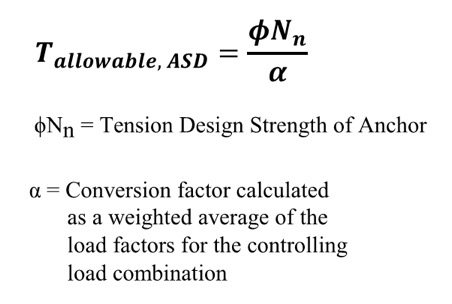
So what do you do now? Well, there is some guidance provided by ICC-ES for manufacturers to convert calculated SD capacities to ASD allowable load values. Since there is no conversion procedure stated in the IBC or referenced standards, designers may want to use this generally accepted method for converting anchor capacities designed using ACI 318. ICC-ES acceptance criteria for post-installed mechanical and adhesive anchors (AC193 and AC308) and cast-in-place steel connectors and proprietary bolts (AC398 and AC399) outline a procedure to convert LRFD capacities to ASD using a weighted average for the governing LRFD/SD load combination. So if the governing load combination for this anchor was 1.2D + 1.6L and the dead load was 1,000 pounds and the live load was 4,000, then the conversion factor would be (1.2)(0.2) + (1.6)(0.8) = 1.52 (keep in mind that the LRFD/SD capacity is divided by the conversion factor in the ICC-ES equation shown here for tension).

Right away, there are a few things that you may be thinking:

  1. What about load factors that may exist in ASD load combinations?
  2. It may just be easier to just recalculate my design loads using LRFD/SD combinations!
  3. The resulting allowable loads will vary based on the load type, or combination thereof.
  4. If the ACI 318 design strength is limited by the steel anchor, then the conversion will result in an allowable load that is different from the allowable load listed for the steel element in AISC 360.

Let’s take a look at these objections one by one.

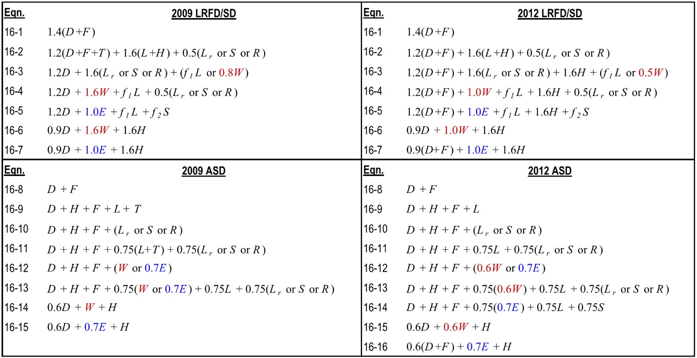
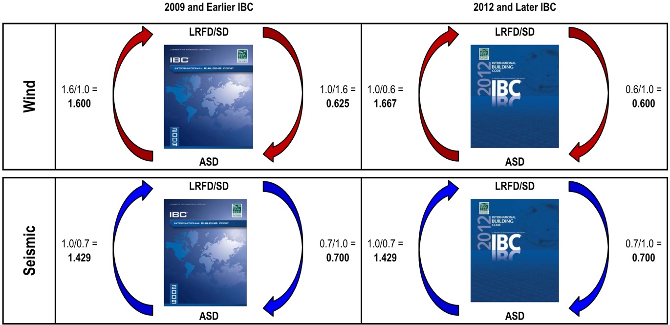
Item 1: Since unfactored earthquake loads are determined at the ultimate level in the IBC, they have an LRFD/SD load factor of 1.0 and an ASD load factor less than 1.0, which is also true for wind loads in the 2012 and 2015 IBC (see graphic below). Using the LRFD/SD load factor of 1.0 obviously does not convert the capacity from LRFD to ASD so you must also account for ASD load factors when calculating the conversion factor. To do so, instead of just using the LRFD load factor, use the ratio of LRFD Factor over ASD Factor. So if the governing load combination for an anchor was 0.9D + 1.0E and the dead load was 1,000 pounds and the seismic load was 4,000, then the conversion factor would be (0.9)(0.2) + (1.0/0.7)(0.8) = 1.32.

ICC-ES-equations

Item 2: Even though the weighted average conversion requires you to go back and dissect the demand load into its various load types, often this can be simplified. ICC-ES acceptance criteria permit you to conservatively use the largest load factor. The most common application I run into is working with ASD-level tension loads for wood shearwall overturning that must be evaluated using SD-level capacities for the concrete anchorage. Since these loads almost always consist of wind or seismic loads, using the largest factor is not overly conservative. Depending on the direction in which you are converting the demand loads or resistance capacities, the adjustment factors are as shown in the figure below. Affected Simpson Strong-Tie products now have different allowable load tables for each load type. (For examples, see pp. 33-36 of our Wood Construction Connectors catalog for wind/seismic tables and pp. 28-30 of our Anchoring and Fastening Systems catalog for static/wind/seismic tables.)

IBC-ealier-later

Item 3: I am unsure whether there is any sound rationale for having allowable loads for an anchor resisting 10% dead load and 90% live load differ from those of an anchor that resists 20% dead load and 80% live load. Perhaps a reader could share some insight, but I just accept it as an expedience for constructing an ASD conversion method for a material design standard that was developed for SD methodology only.

Item 4: We have differing opinions within our engineering department on how to handle the steel strength component of the various SD failure modes listed in ACI 318. Some believe all SD failure modes in ACI 318 should be converted using the load factor conversion method. I side with others who believe that the ASD capacity of a steel element should be determined using AISC 360. So when converting SD anchor tension values for a headed anchor, I would apply the conversion factor to the concrete breakout and pullout failure modes from ACI 318, but use the ASD steel strength from AISC 360.

Finally, I wanted to point out that the seismic provisions in ACI 318, such as ductility and stretch length, must be considered when designing anchors and are not always apparent when simply converting to ASD. For this reason, I usually suggest converting ASD demand loads to SD levels so you can use our Anchor Designer™ software to check all of the ACI 318 provisions. But for some quick references, we now publish tabulated ASD values for our code-listed mechanical and adhesive anchors in our C-A-2016 catalog —  just be sure to read all of the footnotes!

Strong-Wall Bracing Selector: Bridging the Gap between Engineered Design and Prescriptive Construction

Asking a structural engineer to design wall bracing under the IRC® can be like asking a French pastry chef to bake a cake using Betty Crocker’s Cookbook. The temptation is to toss out the prescriptive IRC recipe and design the house using ASCE 7 loads and the AWC SDPWS shear wall provisions per the IBC®. But if only a portion of the house needs to be engineered, there may be an easier option.

The prescriptive IRC states an IBC engineered design “is permitted for all buildings and structures and parts thereof” but the design must be “compatible with the performance of the conventional framed system.” But how exactly does an IRC braced wall panel perform? The code doesn’t come right out and tell us, but there are two bracing methods that are essentially shear walls masquerading as braced wall panels: Method ABW and Method BV-WSP. Backing into their allowable loads gives us the key to determining equivalence and eliminates the need to develop lateral forces.

But before you can bust out the slide rule and start crunching numbers, you need to figure out how much bracing the prescriptive code requires. We developed our Wall-Bracing-Length Calculator in 2010 to help designers do just that. And last month, we launched our Strong-Wall® Bracing Selector tool to make it easier to specify equivalent solutions for tricky situations.

Strong-Wall Bracing Selector
Wall-Bracing-Length Calculator

You can export the required lengths (and project information) from the Wall-Bracing-Length Calculator directly into the Strong-Wall Bracing Selector or you can manually enter in the required lengths. The selector app will provide a list of Strong-Wall panels that have an equivalent length, evaluate their anchorage loads and return a list of pre-engineered anchor solutions for a variety of foundation types.

If you’re familiar with our Strong-Wall Prescriptive Design Guide (T-SWPDG10), the selector automates this 84-page document in just a few steps. One big upgrade is the ability to select a solution to meet the exact amount of bracing that is required. If you needed 2.8-ft. of wall bracing, you have to round up to the tabulated 4-ft. solutions if you are using the guide, but now you can select a wall solution that is equivalent to 2.8-ft., which might mean a smaller wall width or better anchor options. You also have the ability to save the selector file for later modifications, create a PDF of the job-specific output, or email the PDF directly from the program.

Strong-Wall Prescriptive Design Guide

So next time you get asked to “design” some wall bracing, see if our Wall-Bracing-Length Calculator and Strong-Wall Bracing Selector might save you some time. There is a tutorial and a design example on the Bracing Selector web page, but it’s very easy to use so you may just want to dive right in. I should also point out that the Strong-Wall SB panels have not yet been implemented into the program, but bracing information for them is available on strongtie.com in posted letters for wind (L-L-SWSBWBRCE14), seismic (L-L-SWSBSBRCE14), and seismic with masonry veneer (L-L-SWSBVBRCE14).

Let us know what you think of this new tool in the comments below.


Newest Connector to Satisfy Code

“Does Simpson Strong-Tie write the building code?”

If you work at Simpson Strong-Tie, you get asked this question from time to time when you’re in the field. Over the years, I’ve heard it dozens of times, and because the answer is obviously “no,” it makes you wonder why this belief persists with so many people in the industry. Well, here is my theory: We develop and test products for new code provisions faster than it takes states to adopt the newest codes. So a designer, contractor or building official will often hear about a new Simpson Strong-Tie product or tested application that fills a need before their state building code even defines what that need is. Here are some recent examples:

  • The FWAZ foundation anchor released in 2007 for a 2006 IRC provision that addresses soil pressure loads on basement walls
  • Strong-Drive® SDS screw testing for deck ledgers published in 2008 as alternates to bolts and lags that weren’t prescribed in the IRC until the 2009 edition
  • The DTT2 deck tension tie released in 2009 is used for a 2009 IRC provision that addresses lateral loads on decks
  • BPS ½ -6 bearing plate released in 2011 to address new provisions for shear wall bearing plates in the 2008 SDPWS, which is referenced in the 2009 and 2012 IBC

The latest example is the DTT1Z deck tension tie. Two of our engineers, Randy Shackelford and David Finkenbinder, attended the ICC hearings that resulted in the new 2015 IRC. As soon as a new provision was passed to provide an alternate 750-pound deck lateral load connection (submitted by Washington Assoc. of Building Officials, not Simpson Strong-Tie) we began working on a connector designed to do the job. After several months of R&D, field trials and new tooling, our presses began to stamp out the first production run of the DTT1Z to meet the 2015 IRC provision on December 30, 2014.

DTT1Z Production Run
2015 IRC Detail
2015 IRC Detail

The IRC detail shows an ideal condition where the bottom of the deck joist lines up with the wall plates in the house. We tested this application, but we also wanted to support variations that may come up in the field. The results of this testing appear in our T-C-DECKLAT15 technical bulletin. We also tested the DTT1Z with our Strong-Drive® SDWH Timber-Hex HDG screw and our Titen HD® concrete screw anchor so it can be used in a variety of applications, including prescriptive wall bracing and (very) light shear walls. Many of these applications are covered in the code report (ER130) that was completed just this past week.

2015 IRC Test Setup
Test setup: 2015 IRC detail
Joist Scab Test Setup
Test setup: Blocking attached to side of joist
Joist Blocking Test Setup
Test setup: Blocking running between joists


If you are interested in reading more about the new IRC deck provisions, Randy wrote about them in his Code Corner column in the current Structural Report and David wrote about them in this blog last August.

In case you are wondering how I respond when asked if we write the code, lately I have been answering it with another question: No, but do you know who is responsible for writing the code? My answer to this is “all of us.” If you don’t like what is in there now, work with an association that represents your interests (NCSEA for a lot of us) to submit a code-change proposal, or even submit one yourself. There is no guarantee it will get in, but if it involves a connection, I can guarantee we will get working on it right away!

Let us know if you see a need for a new connection product. If you already have a product idea and would like to work with us to develop it, you can more-formally submit it here.

Wood Shear Wall Design Example

Two weeks ago, I had the chance to present to the Young Members Group of the Structural Engineering Association of Metro Washington on the topic of Multi-Story Light-Frame Shear Wall Design. With all of the large firms in the D.C. area, it wasn’t a big surprise to find out that only about one-third of the group had experience with light-frame shear wall design.

However, while researching civil/structural engineering programs in the Midwest and Northeast last week (for our Structural Engineering/Architecture Student Scholarship program), I was disappointed to find that only about a quarter of the top engineering programs offer a wood design course. So I thought it might be helpful to post a wood shear wall design example this week.

The example is fairly basic but includes an individual full-height and perforated shear wall analysis for the same condition. The design is based on wind loading and SPF framing, both common in the Midwest/Northeast, and is based on the provisions and terms listed in the 2008 Special Design Provisions for Wind and Seismic (SDPWS), available for free download here, along with the recently posted 2015 version.

Multi-Story Shear Wall Example: Wind Loads with SPF Framing

Given:SE blog 1

  • 2012 IBC & 2008 SDPWS
  • 3-Story Wood Framed Shear Wall Line
  • ASD Diaphragm Shear Forces from Wind as Shown
  • Wall and Opening Dimensions as Shown

Solution:

  1. Determine total shear force in each shear wall line.
  2. Determine the Induced Unit Shear Force, v, for use with both shear wall types and the Maximum Induced Unit Shear Force, vmax, for the perforated shear wall collectors, shear transfer, and uniform uplift. Note the following:
    1. vmax requires the determination of the Shear Capacity Adjustment Factor, CO, for the perforated shear wall.
    2. The SDPWS provides two methods for determining CO, a tabulated value or a calculated value. This example uses the more precise calculated value.
    3. The perforated method requires the collectors be designed for vmax and the bottom plate to be anchored for a uniform uplift equal to vmax (as illustrated in the following figure).

SE blog 2

SE blog 43. Determine the Tension, T, and Compression, C, forces in the chords (assume no contribution from dead load for this example). Note the following:

    1. Reverse wind loading will require a mirror image of the T & C forces shown in the following figure.
    2. The tension forces, T, shown in the example reflect the cumulative tension forces as they are transferred down from post-to-post, as is typical with traditional holdowns. For continuous rod systems like ATS, the incremental tension forces (resulting from the unit shear, vor vmax, at that level only) must also be determined as shown in the shear wall specification table at the end of this example.

SE blog 5

SE blog 5 SE blog 64. Determine sheathing material and fastening pattern based on v calculated in Step 2. The table below is based on 7/16″ wood structural panel sheathing values in SDPWS Table 4.3A.

SE blog 7

    1. Individual Full-Height Shear Wall:

i.     v3=227 plf: Use 7/16 OSB with a 6:12 nailing pattern which has an allowable load of 336 plf

ii.     v2=409 plf: Use 7/16 OSB with a 4:12 nailing pattern which has an allowable load of 490 plf

iii.     v1=591 plf: Use 7/16 OSB with a 3:12 nailing pattern which has an allowable load of 630 plf

B. Perforated Shear Wall (apply CO factor to allowable shear capacity):

i.     v3=227 plf: Use 7/16 OSB with a 6:12 nailing pattern which has an allowable load of 255 plf

ii.     v2=409 plf: Use 7/16 OSB with a 3:12 nailing pattern which has an allowable load of 479 plf

iii.     v1=591 plf: Use 7/16 OSB on both sides of the wall with a 4:12 nailing pattern which has an allowable load of 338*2=676 plf

5. Size the posts for compression. Simpson provides some useful tables in the back of the connector catalog with allowable tension and compression loads for a variety of sizes, heights, and species of posts.

6. Select holdowns for the tensions loads and verify post sizes are sufficient. For higher aspect ratio shear walls, the post size and holdown type may significantly reduce the moment arm between center of tension and center of compression, resulting in higher tension and compression forces.

The tables below show the shear wall specification for the walls in the example in a typical format. Note that they do not include some detailing that is required for items such as the uniform uplift force on the bottom plate of all perforated shear walls, or the perforated shear walls with OSB sheathing on both sides.

SE blog 8

There are different ways to address the loads, so let us know if you would do anything differently in your designs.

Engineering Fees

Guest blogger Shane Vilasineekul, engineering manager

[Simpson Strong-Tie note: Shane Vilasineekul is the Simpson Strong-Tie Engineering Manager for the Northeast U.S. and one of our guest bloggers for the Structural Engineering Blog. For more on Shane, see his bio here.]

Are you finding it difficult to keep your fees competitive?

“Codes are becoming more complex.”

“Builders are demanding lower construction costs.”

“If I don’t allow this they will find an engineer who will.”

“Competition is stiffer.”

“New proprietary systems take too long to evaluate.”

“We have less time to do our job”

“Architects don’t give us enough to work with.”

“Other engineers are not doing it right.”

Working at Simpson Strong-Tie for 15 years, I have had the opportunity to speak with thousands of engineers and these are recurring themes. Some of these issues are way above my pay grade, but there may be something each of us can do to help keep our profession healthy.

A few years ago we had Susan Dowty from the California offices of S.K. Gosh speak at our SEA of Ohio conference. After her presentation, she stuck around to hear Steven Regoli from the Ohio Board of Building Standards. The gist of his presentation was that Ohio building officials don’t have the authority to reject sealed plans or even require calculations to be submitted unless there is clear evidence of a code violation. Midway through, a very lively discussion broke out between Susan and Steven about the responsibilities of plans examiners as they relate to structural design. On one side you have plans examiners who are licensed engineers and perform something akin to a peer review, and on the other side you have plans examiners with little engineering background that rely on the licensed engineer to ensure structural provisions are met. With some exceptions, the first view is held by many western states and the latter by many states in the South, Midwest and East Coast.

SE Blog

So how does this affect engineering fees? Well, when all it takes to collect a fee is a sealed set of structural plans, the temptation is there to cut corners in the design process and, in an increasingly competitive market, provide clients with a building that costs less to construct than one properly designed. I take pride in working in a profession that holds ethics in such high regard, but it only takes a few to give in and disrupt the market in a particular region. It seems like these “few” are gaining in numbers the last several years. Without proper checks and balances, this trend could continue.

So what can we do about it? I don’t think local government would be open to increasing the payroll for building departments to hire more engineers to review plans (building departments in Ohio saw some of the first and most severe cuts during the recent recession), but maybe we can help raise the bar for structural plan review. Steven Schaefer, the founder of Schaefer structural engineers in Cincinnati, decided years ago to take it upon himself to educate Ohio building departments on the fundamentals of structural engineering. He regularly presents at their meetings and has even created a guide to help plan reviewers look for proper load paths and lateral force-resisting systems. Next week he will be presenting four courses at their state conference and will be honored with an award for all his efforts over the years. We may not all be able to have the same impact, but most of us could spare a few hours each year to work with our local engineering association to reach out to building departments and offer training and support.

Leave a comment if you have some ideas on how to maintain our high standards, or better yet, share some successes you have seen in your area.

Ten Apps for Engineers

Shane Vilasineekul
Guest blogger Shane Vilasineekul, engineering manager

When Simpson Strong-Tie began supporting the use of iPads by employees, it was about the same time my Blackberry contract was expiring, so I decided to go all-in with Apple® and get an iPhone® 4s and an iPad®. Since mobile devices will not replace the heavy lifting required from most engineers’ computers, I wanted to find some apps that complemented my PC use and made me more efficient when I was away from my desk.  After reading reviews and trying out a few, I eventually came up with a list of apps that I recommend. None were developed for engineers, but they are the ones I use most often. Let me know what you think of these or any of your favorites that I missed.

DropBox
DropBox
Google Drive
Google Drive

1. File Sharing Apps: My initial search was for a way to share files between my Apple devices and my PC. Since there is limited space in the free cloud services, I use two: Dropbox (free) for work files and Google Drive (free) for home files. Install the apps on your mobile devices and the software on your computers, create and log into your account, and you are ready to access/modify/share any of these files on any device. Both of these apps are seamlessly integrated into many other apps.

Notability
Notability

2. Organization: I am not the most organized person, so I wanted an app that would help me keep track of my many notes. After trying a few different ones, I settled on Notability ($3). I can take handwritten or typed notes, insert a picture of things like a jobsite photo or a paper handout, draw a sketch, or even insert an audio recording. Best of all, I can organize the notes in folders within the app and also back them up as PDF files to Dropbox.

SlideShark
SlideShark

3.  Presentations: I regularly give PowerPoint presentations, so I started using an app called SlideShark (free) and got hooked. It is simple and remains true to the look of the original PowerPoint program. With the current version, I can access files on my DropBox account, play embedded videos, and use my iPhone as a remote when my iPad is connected to a projector. Although I still present with my trusty laptop most of the time, SlideShark is also great for practicing a presentation on a mobile device anywhere you find yourself with a few spare minutes.

MyScript Calculator
MyScript Calculator

4. Calculator: I was shocked to find that my iPad didn’t have a built-in calculator app. I tried a few free ones, but never really liked them. Then MyScript Calculator (free) came out last year, which solves handwritten equations like the one shown in the icon. Now I look for reasons to use it. It won’t ever replace my TI-85, but I am not sure I want it to.


iBooks
iBooks
iBooks Shelf
iBooks Shelf

5. Reference Guides: I like the idea of having electronic versions of my codes and referenced standards all saved in my iPad. Some of the PDF files I purchased allow me to save them in iBooks (free); others shown in the screenshot are just covers. On a side note, ICC has all of their codes online, broken into sections (as opposed to a single PDF). It’s great for sending links of specific code language to people that don’t own the code.

GoodReader
GoodReader

6. Editor Apps: There are tons of PDF editing apps out there. I asked around to see what other engineers use and decided on GoodReader ($5). I have been pretty happy with it, mostly using it to mark up PDF files I am reviewing.


PhotoSynth
PhotoSynth

7. Photos: When out on a jobsite, there is no better way to capture information than with a picture. But when everything can’t fit inside the viewfinder, PhotoSynth (free) is a great tool to capture the surroundings. Immersive 360° images  can be posted online, shared, or viewed within the app. Here are links to a couple of mine: Hurricane Sandy, Columbus Test Lab.

SnapSeed
SnapSeed

8. Photo Editing: While on the topic of photos, I use Snapseed (free) whenever I need to edit them. It is simple and intuitive, but powerful enough to get the job done.


Scanner Pro
Scanner Pro

9. Scanner Pro ($3) turns your camera into a scanner. Take a picture of a paper document, then locate the corners of the paper within the app and turn it into a PDF file that scales and stretches it to look like a scan instead of a snapshot.


Paper
Paper
Sketchbook Express
Sketchbook Express

10. Sketch Apps: My favorite apps for sketching a new connector idea, illustrating a concept or just doodling, are Paper (free) and SketchBook Express (free). Paper is more free-form and natural, while SketchBook has more tools and provides more precise control. They are free, so give them both a try.

*Apple, the Apple logo, iPhone and iPad are trademarks of Apple Inc., registered in the U.S. and other countries.*

Hurricane Sandy, One Year Later

Shane Vilasineekul
Guest blogger Shane Vilasineekul, engineering manager

[Simpson Strong-Tie note: Shane Vilasineekul is the Simpson Strong-Tie Engineering Manager for the Northeast U.S. and one of our guest bloggers for the Structural Engineering Blog. For more on Shane, see his bio here.]

The end of this month will mark the one year anniversary of Superstorm Sandy hitting the coastlines of New Jersey, New York, and surrounding states. A lot of construction has taken place in the last 12 months, but most of the rebuilding will occur over the next few years. The boardwalks were a high priority because of their effect on tourism, which is so vital to the local economies, and most of them have been completed (see my previous post about rebuilding after Sandy here). Now the focus has shifted to repairing, raising, and rebuilding homes.

Boardwalk under construction.
Boardwalk under construction. Image credit: Matt Cross, Simpson Strong-Tie.

I am writing this while sitting in the Newark airport, headed home after presenting one of our workshops on high wind design. The workshop was held at a hotel in Manahawkin, New Jersey that happened to be used last year by residents displaced by the storm, including some of the architects and engineers in attendance this morning. After talking to a few of them at the breaks, it sounded like they are struggling with the current state of building provisions, which were quickly put in place to ensure rebuilt properties are more resilient, including new flood elevations and renewed focus on code compliance.

Continue Reading