

In an ideal world, a building is envisioned and a structural engineer begins the structural design. When the decision to use roof trusses is made, a component manufacturer is promptly involved in the design process. Using the loads and design parameters from the structural engineer, the trusses are designed and those designs are provided back to the engineer. The structural engineer then incorporates the truss designs into the building, transfers the loads through the structure and designs all the structural elements, bracing and connections necessary to provide a continuous load path down to the foundation. Finally, working from the complete and detailed plans, the contractor constructs the building flawlessly. Perfection!
But let’s get back to reality, where buildings are often designed and ground broken by the time the trusses are designed. The building Designer creates a roof framing plan to analyze and transfer the loads between the roof system and the rest of the building, and then designs the building (from the top plate down) accordingly. The component manufacturer (CM) eventually gets the plans and uses them to create a truss placement diagram and gather the truss design criteria. The CM then communicates the truss design parameters to the truss design engineer, who designs each of the individual trusses. The CM provides those truss designs and the truss placement diagram back to the building Designer. So far so good, right?
If every building were rectangular with a gable-style roof, this process would be fairly simple and hassle-free. But buildings are often more complicated than that. Roof systems can get very complex, so things don’t always go according to plan…such as when a wall that was intended to be non-load bearing gets used as a bearing location for the trusses; or when the CM moves a girder to a different location that works better for the trusses. Or maybe a truss can’t be designed for the entire span and an additional support is needed. In some cases, the CM may even flip the direction of the trusses completely because it results in a more efficient (lower-cost) truss package – that’s better for the building, right?
Changes during the design process can result in additional labor, material and cost. In today’s fast-tracked world, how can these expenses be avoided? Below are some suggestions from a truss Designer’s perspective.
Know each party’s design responsibilities
This may not seem like it has much to do with minimizing changes during the design process, but some problems arise from the fact that there is not always a common understanding of each party’s responsibilities. One misconception is that truss design engineers design an entire roof system, and they design the roof truss system to work within the framework of the building as set forth in the building structural plans. This is not true! Truss design engineers design single components, not systems. They do not even see the building Designer’s plans. It is the CM that receives the construction documents to obtain the truss design criteria and requirements. They in turn communicate the truss design parameters to the truss design engineer.
It is also important to understand the role the truss placement diagram plays in the overall process. This is a commonly misunderstood document, because many people think this is an engineered document prepared by the truss design engineer. Not only do truss design engineers not prepare these documents, they do not even review them. Instead, the CM creates the truss placement diagram after reviewing the construction documents. A truss placement diagram is only intended to identify the assumed location for each truss and serve as a truss installation aid. In fact, the truss industry intentionally changed the description of this document at one point from “truss placement plan” to “truss placement diagram” because the word “plan” has a connotation associated with engineering and design, and a truss placement diagram does not involve either of those.
Understanding how the truss industry operates and the responsibilities each party has in the design process will prevent incorrect assumptions from being made. If you find yourself saying, “I’m sure the truss design engineer will check this and take care of it…,” you probably need to think again.

The clearer the specifications, the better
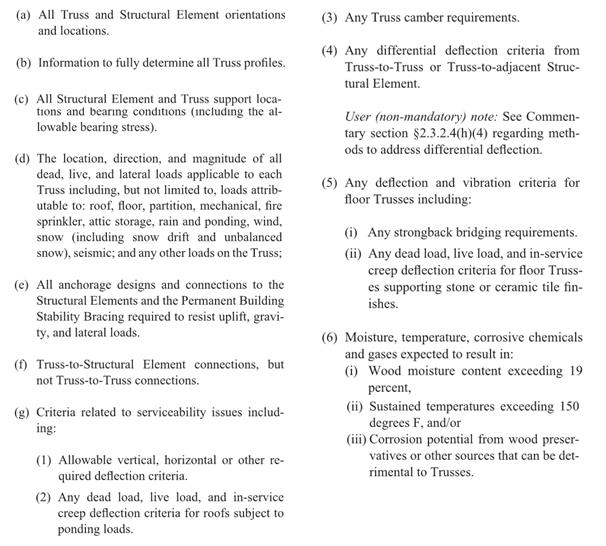
This may seem obvious, but do the construction documents contain all of the information necessary for the preparation of the truss design drawings? ANSI/TPI 1 specifies the required information in the construction documents (see text box below). Anything less than this information will mean assumptions need to be made during the creation of the truss placement diagram and the design of the trusses. The building Designer can also specify additional requirements to help ensure that the trusses they get are the trusses they want. In short, the more complete, accurate and detailed the construction documents are, the better the design process will be.
Review, review, review
It is the building Designer’s responsibility to review (and approve or reject) both the truss placement diagram and the individual truss design drawings for conformance with the overall building design. As mentioned earlier, the truss design engineer is solely responsible for the design of the individual trusses; they do not review the entire truss system and they do not check to see that the truss placement diagram meets the intent of the framing plan and specifications. Further, the component manufacturer relies on the completeness and accuracy of the information in the construction documents to create the truss placement diagram and to communicate the truss design requirements to the truss design engineer. Therefore, the success of the building’s construction depends on the building Designer’s thorough review of the truss submittal package.
Collaboration is key
Building Designers know what is best for the overall building; component manufacturers know what is best for the trusses. The best-case scenario is when the building gets the best of both. This requires collaboration during the planning stages, so that the strengths of both parties can be utilized to their maximum potential. A building Designer who finds out from the CM what the best setback distance is for a particular hip roof will not only minimize changes to the design downstream, but will also likely end up with a lower-cost building. On the other hand, a building Designer who provides some input into the actual truss designs, such as strategically placed webs in a string of trusses, will end up with a more efficient, permanent bracing plan that can even be included in the original construction documents.
Some may think the answer to this design process challenge is to let the building Designers design the trusses themselves; that all they need is the truss design software and they can design the trusses as part of their building design. But the truss industry knows that truss design software cannot replace the ingenuity and creativity of talented CMs who have a passion for what they do; just the same way that engineering software cannot ever replace an experienced engineer. That is why the truss industry continues to work hard to make it easier to collaborate, in lieu of providing truss design software to people outside of the component manufacturing industry. In this way, everyone’s skill sets can be fully utilized.
What do you think about this challenge? Let us know your thoughts in the comments below!

Several things to consider when checking wood truss shop drawings.
1) The truss designers never seem to consider uplift on overhangs. Many will just use MWFRS and neglect components and cladding uplift.
2) On structures like entrance canopies they design them as enclosed structures for wind instead of open structures which have higher uplift forces.
3) Gable end trusses are also a problem because they don’t design for wind perpendicular to the truss span.
4) They often don’t consider lateral deflection for scissor trusses which can be a problem for longer spans.
What is really concerning is that a lot of buildings get built without anyone reviewing the trusses.
I have a question on the lateral design for truss elements. If for example on a gable end the truss needs to transfer 200plf from the top chord to the bottom chord of the truss then to the wall top plates below, and then into the shearwalls. If the building is designed as a plywood shear wall building with an R=6.5 – What methodology is used to design the truss for the 200plf ? What is the safety factor on the truss design? What is the post yield behavior of that truss and at what force would that occuor at? Do I need to increase the design force on the truss to make sure it is not the element that will yield before the plywood shearwall and what is the post yield behavior expected to be? How is the bracing to be designed to keep the typically 2x width element from buckling with the shear loads.
Generally you would extend the plywood or OSB sheathing up to the top of the truss. If there is a horizontal joint in the sheathing where the wall and truss are joined together shear plates such as Simpson LTP4 should be installed at the joint to transfer the shear from the sheathing on the side of the truss to the wall sheathing.
Generally on gable end trusses the 2x is in the weak direction for wind perpendicular to the end gable. Depending on the height of the gable one or two strongbacks may be needed to brace the truss web verticals in the weak direction.
The gable trusses generally consist of a top and bottom chord with flat verticals along their length and are not designed to transfer in-plane lateral shear load from the top chord. So, as NITTANYRAY describes, standard practice is to extend the wall sheathing to the top of the truss.
In answer to your question about safety factors on trusses, it varies by component – truss plate tooth withdrawal, truss plate shear, truss plate tension, or wood member failure. This FAQ from Structural Building Components Magazine discusses truss safety factors in some detail:
http://www.sbcmag.info/sites/sbcmag.info/files/Archive/2003/mar/0303%20FAQ.pdf
The overall safety factor of a completed truss should be between 2 and 2.5.
If you are specifying that the truss transfer the lateral load (rather than running the wall sheathing all the way up), the truss should be designed for over-strength level forces per ASCE 12.4.3. Designing the truss for over-strength (Omega blog post – http://seblog.strongtie.com/2013/04/the-omega-factor/) forces will ensure that the truss does not yield. Since designing for these amplified forces is difficult, it is much more economical to detail the wall sheathing to extend to the top of the truss – even if that requires a bit more sheathing and blocking.
So if you design the wall sheathing to extend to the top of the truss – The design for that would be per the wood shear wall tables? Then the top chord would need to be designed with lap splices and 2×4 studs perpendicular to the sheathing. How is using a single truss ply with plywood sheathing meet the requirements for a shear wall? Is there testing on an assembly like this?
The link to the Omega blog post is not working – can you repost?
Hi Tim – This link should work: http://seblog.strongtie.com/2013/04/the-omega-factor/ You can also search for “The Omega Factor” using the “Search this Blog” box on this page.
According to the author, the truss design engineer does not review the building framing plan or the truss placement diagram. Does the component manufacturer just provide a list with the dimensions and loads for every truss? If so, the component manufacturer sounds like a middle man that is just there to add to any potential confusion.
From Kelly Sias:
Component Manufacturers play a much more important role than
simply communicating the truss design requirements. Component
Manufacturers have highly skilled technicians that use the truss design software to input design parameters and create preliminary designs. Not only does this enable them to prepare quotes, but it also gives them the opportunity to do what they do best – optimize. From optimal webbing configurations to material selection and splice locations, CMs are the masters of optimization, since they know best what and where their manufacturing strengths and efficiencies come from. Once they have done their part, all of the truss design parameters, as well as all of the CM’s design preferences (aka optimizations), lumber and plate inventories, are transmitted electronically to the truss design engineer. The truss design engineer then uses all of that information to create and design not only an engineered truss that meets all of the requisite design requirements, but one that is also optimal for the manufacturing environment (thanks to the input from the CM!). The roles of the CM and the truss design engineer are somewhat analogous to the roles of an Architect and an EOR on a project – they both serve very different, yet equally important, roles. Just as most project engineers do not have architectural expertise, most truss design engineers do not have truss manufacturing/optimization expertise.
For anyone involved in the design/construction industry that has never visited a truss plant, or at least not recently, it is strongly encouraged that you do so. To see a Component Manufacturing operation at work, from the sales and design office through cutting, manufacturing and preparing for delivery, it is not only impressive but also eye-opening. There are many Component Manufacturers who are willing and happy to open their doors and give you a tour. Reach out to them; it could turn out to be the best business decision you make today.