

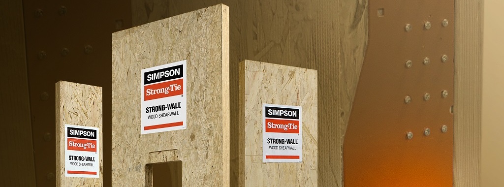
In last week’s blog post, we introduced the Simpson Strong-Tie® Strong-Wall® Wood Shearwall. Let’s now take a step back and understand how we evaluate a prefabricated shear panel to begin with.
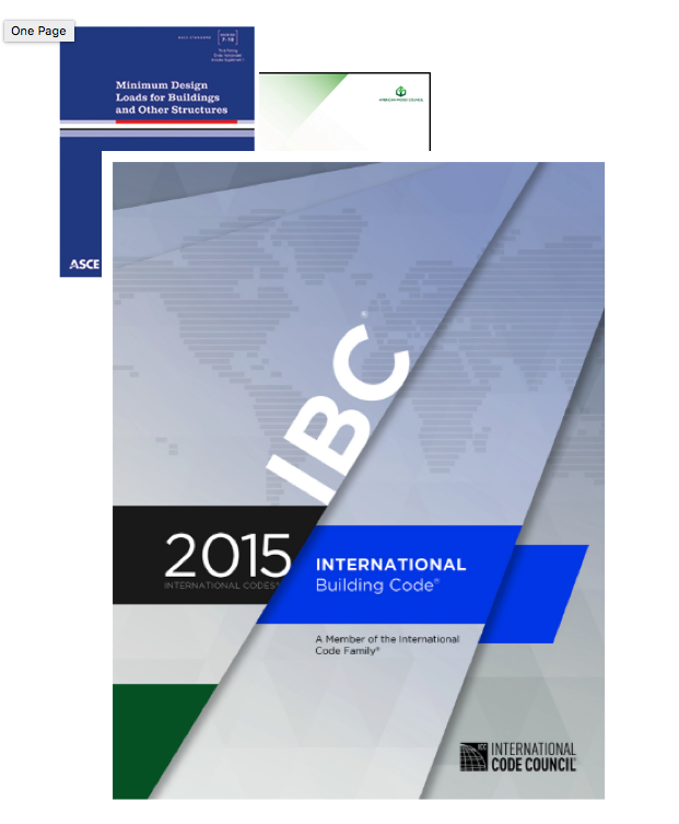
First, we start with the International Building Code (IBC) or applicable state or regional building code. We would be directed to ASCE7 to determine wind and seismic design requirements as applicable. In particular, this would entail determination of the seismic design coefficients, including the response modification factor, R, overstrength factor, Ωo, and deflection amplification factor, Cd, for the applicable seismic-force-resisting system. Then back to the IBC for the applicable building material: Chapter 23 covers Wood. Here, we would be referred to AWC’s Special Design Provisions for Wind and Seismic (SDPWS) if we’re designing a lateral-force-resisting system to resist wind and seismic forces using traditional site-built methods.
These methods are tried and true and have been shown to perform very well in light-frame construction during wind or seismic events. But over the years, many people have come to enjoy things like lots of natural light in our homes, great rooms with tall ceilings and off-street secure parking.
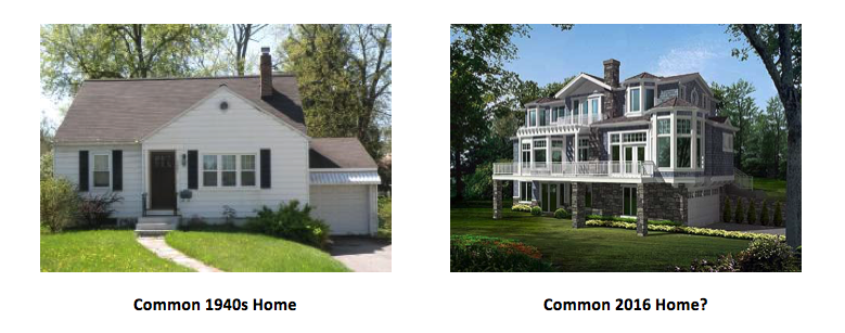 Due to Shearwall aspect ratio limitations defined in SDPWS as well as the strength and stiffness limitations of these traditional materials – including wood structural panel sheathing, plywood siding and structural fiberboard sheathing, to name a few – we’re left looking for alternative solutions. Thankfully, the IBC has left room for the use of innovative solutions beyond what’s explicitly stated in the code. Section 104.11 of the 2015 IBC provides the following provision:
104.11 Alternative material, design and methods of construction and equipment
The provisions of this code are not intended to prevent the installation of any material or prohibit any design or method of construction not specifically prescribed by this code, provided that any such alternative has been approved. An alternative material, design or method of construction shall be approved where the building official finds that the proposed design is satisfactory and complies with the intent of the provisions of this code, and that the material, method, or work offered is, for the purpose intended, not less than the equivalent of that prescribed in this code in quality, strength, effectiveness, fire resistance, durability and safety…
104.11.1 Research Reports. Supporting data, where necessary to assist in the approval of materials or assemblies not specifically provided for in this code, shall consist of valid research reports from approved sources.
104.11.2 Tests. Whenever there is insufficient evidence of compliance with the provisions of this code […] the building official shall have the authority to require tests as evidence of compliance…
Research Reports
The route we at Simpson Strong-Tie typically take is to obtain a research report from an approved source, i.e., the ICC Evaluation Service or the IAPMO Uniform Evaluation Service. Each of these evaluation service agencies publishes acceptance criteria that have gone through a public review process and contain evaluation procedures. The evaluation procedures might contain referenced codes and test methods, analysis procedures and requirements for compatibility with code-prescribed systems.
Prefabricated Panel Evaluation
Let’s once again take a step back and consider the function of our Strong-Wall® shearwalls. They’re prefabricated panels intended to provide lateral and vertical load-carrying capacity to a light-framed wood structure where traditional methods are not applicable or are insufficient. We need to provide a complete lateral load path, which ensures that the load continues through the top connection into the panel and then into the foundation through the bottom connection. To evaluate the panel’s ability to do what we’re asking of it, we use a combination of testing and calculations with considerations for concrete bearing, fastener shear, combined member loading, tension and shear anchorage, panel strength and stiffness, etc.
I could write a five-thousand-word feature story for the New York Times discussing the calculations in great detail, but let’s focus on the more exciting part – testing! Simpson Strong-Tie has several accredited facilities across the country where all of this testing takes place; click here for more info.
Testing Acceptance Criteria
Now to pull back the curtain a bit on the criteria we follow in our testing: We test our panels in accordance with the criteria provided in ICC-ES AC130 – Acceptance Criteria for Prefabricated Wood Shear Panels or ICC-ES AC322 – Acceptance Criteria for Prefabricated, Cold-Formed, Steel Lateral-Force-Resisting Vertical Assemblies, as applicable. These criteria reference the applicable ASTM Standard, ASTM E2126-11, which illustrates test set-up requirements and defines the loading protocol among other things. If you’re interested, the work done by the folks involved with the CUREE-Caltech Woodframe Project, which is the basis for the testing protocol we use today, makes for an excellent read. The CUREE protocol, as it’s known, is a displacement-controlled cyclic loading history that defines how to load a panel. A reference displacement, Δ, is determined from monotonic testing, and the cyclic loading protocol, which is a series of increasing displacements whose amplitudes are functions of Δ, is developed. I’ve provided a graphic depicting the protocol below.
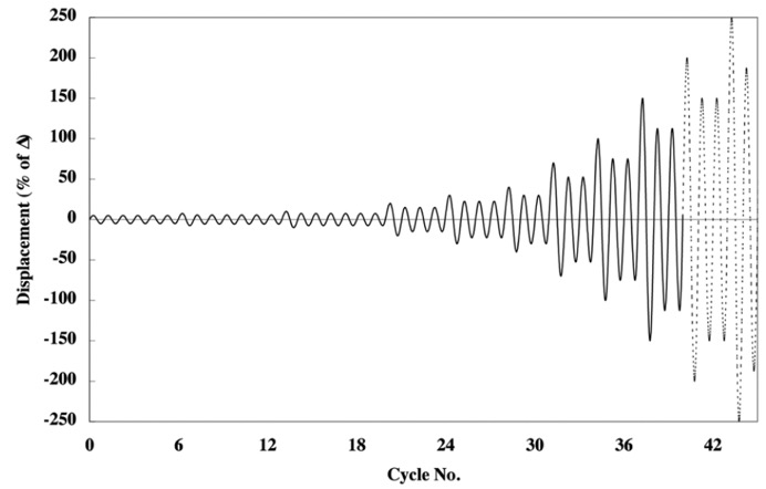
When prefabricated shear panels are subjected to the loading protocol shown above, a load-displacement response is generated; we call this a hysteresis loop or curve.
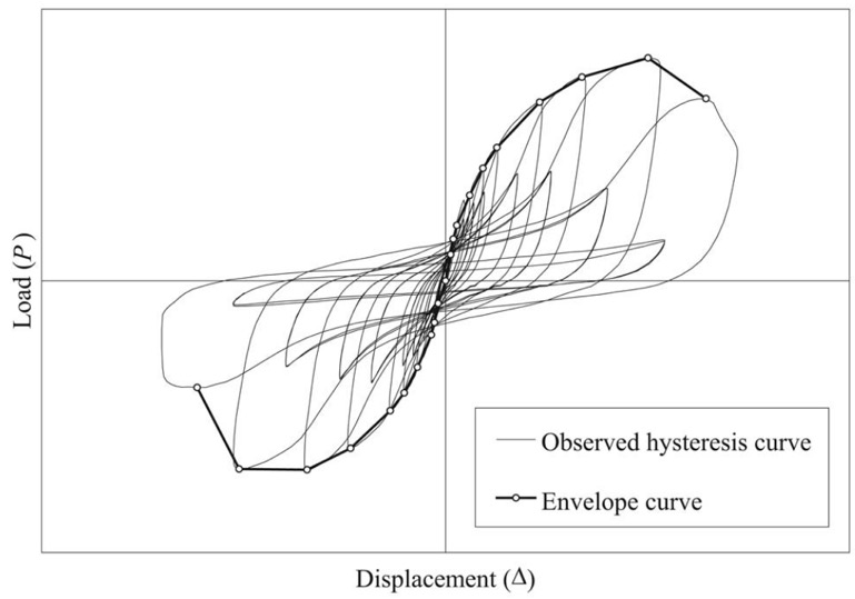
We then use this curve to generate an average envelope (backbone) curve that will be used for analysis in accordance with the procedures defined in AC130 or AC322 as applicable.
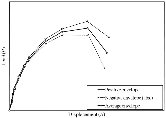
Returning to the acceptance criteria, there are different points of interest on the average envelope curve depending upon whether we’re establishing allowable test-based values for wind-governed designs or for seismic-governed designs. I should also note that both wind and seismic designs consider both drift and strength limits when determining allowable design values.
Wind is fairly straightforward, so let’s start there. While the building code does not explicitly define a story drift limit for wind design, the acceptance criteria do. The allowable wind drift, Δwind, shall be taken as H/180, where H is the story height. The allowable ASD in-plane shear value, Vwind, is taken as the load corresponding to Δwind. I mentioned a strength limit as well; this is simply taken as the ultimate test load divided by a safety factor of 2.0.
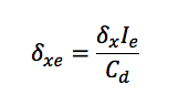
Contrary to wind design, the building code does define a story drift limit for seismic design. ASCE7 Table 12.12-1 defines the allowable story drift, δx, as 0.025H for our purposes, where H is the story height. The strength design level response displacement, δxe, is now determined using ASCE7 Equation 12.8-15 as referenced in AC130 and AC322 as follows:
Where:
- δxe = LRFD strength design level response displacement
- δx = Allowable story drift = 0.025H for Risk Category I/II Buildings (ASCE7 Table 12.12-1)
- Ie = Seismic importance factor = 1.0 for Risk Category I Buildings (ASCE7 Table 1.5-2)
- Cd = Deflection amplification factor = 4.0 for bearing wall systems consisting of light-frame wood walls sheathed with wood structural panels rated for shear resistance (ASCE7 Table 12.2-1)
We then consider the shear load corresponding to the strength level response displacement, VLRFD, and multiply this value by 0.7 to determine the allowable ASD shear based on the seismic drift limit, VASD. Lastly, the seismic strength limit is taken as the ultimate test load divided by a safety factor of 2.5.
Compatibility with Code-Prescribed Methods
We’ve gone through the steps to evaluate the allowable design values for our panels, but we’re not done yet. AC130 and AC322 define a series of criteria to ensure that the seismic response is compatible with code-defined methods with respect to strength, ductility and deformation capacity. Once we verify that these compatibility parameters have been satisfied, we may then apply the response modification factor, R, overstrength factor, Ωo, and deflection amplification factor, Cd, defined in ASCE7 for bearing wall systems consisting of light-frame wood or cold-formed steel walls sheathed with wood structural panels or steel sheets. This enables the prefabricated shearwalls to be used in light-frame wood or cold-formed steel construction. I’ve very briefly covered an important topic in seismic compatibility, but there has been plenty published on the issue; I recommend perusing the article here for more details.
We’ve now followed the path from building code to acceptance criteria to evaluation report. More importantly, we understand why Strong-Wall® shearwall panels are required and the basics of how they’re evaluated. If there are items that you’d like to see covered in more detail or if you have questions, let us know in the comments below.
