


It seems that each major hurricane tends to teach those of us in the construction industry some lesson. With Hurricane Andrew, the lessons were the importance of protection from windborne debris, and the importance of proper construction of gable end overhangs.
There are two main areas where gable ends can fail.
Gable End Failure: Connection Between Top Plate and Gable End Framing
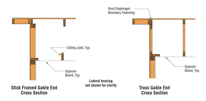
One is a failure of the hinge at the connection between the top plate of the wall and the gable end framing, if the gable end is not balloon-framed with continuous studs. This is now addressed in the International Residential Code. Since 2009, Section R602.3 has required that “Studs shall be continuous from support at the sole plate to a support at the top plate to resist loads perpendicular to the wall. The support shall be a foundation or floor, ceiling or roof diaphragm or shall be designed in accordance with accepted engineering practice.”
For existing construction, the International Existing Building Code specifies a method for retrofitting gable ends in Appendix C. For new construction, Simpson Strong-Tie shows a couple of solutions for bracing top plates of gable ends in our High Wind–Resistant Construction Application Guide on Page 48.
Gable End Failure: Uplift of Roof Decking at the Overhang
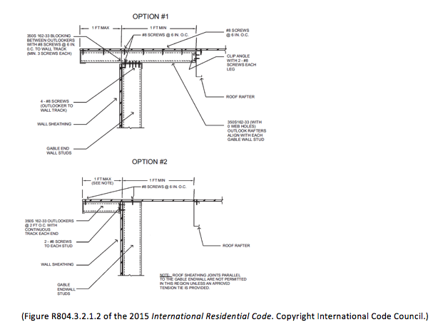
The other common wind-related failure at gable ends is uplift of the roof decking at the overhang. This can be from two causes: inadequate nailing of the sheathing to supporting framing, or inadequate connections of the framing at the rake edge that supports the roof. As far as this author can tell, this area of light construction is not covered in the International Residential Code for wood framing, but it is covered for cold-formed steel framing, where Section R804.3.2.1.2 contains requirements for “Rake overhangs.” The two methods shown are the cantilever outlooker (Option 1) and the ladder outlooker (Option 2).
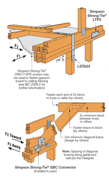
Gable End Overhangs: Cantilevered Outlooker Method
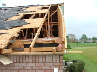
In the photo above, it appears that the cantilevered outlooker method was used, and that there was a failure of the outlooker connections at the gable end and the first full truss. If you look closely, the end nails from the full-height truss that were in the end of the outlookers can be seen in a couple of places.
If a truss roof is used with this method, the gable truss is manufactured 3½” shorter than the others. Then a 2×4 outlooker is placed over the dropped gable, and butted into the side of the adjacent full-height truss. Then the barge or fly rafter is attached to the end of the cantilevered outlooker. At the overhang, wind can cause uplift on both the bottom and top surface. The uplift at the end of the outlooker imparts an uplift force at the gable truss, which must be resisted by a tension connection such as a hurricane tie, and a downward force at the connection to the full-height truss.

Gable End Overhangs: Ladder Outlooker Block Method
The other method commonly used to support the sheathing and the barge rafter is the ladder method. With this technique, lookout blocks are used to connect the barge or fly rafter back to the gable framing. One way this can be constructed is as a full ladder, with parallel fly rafter and ledger with block framing in between. Either this assembly can be constructed on the ground and then raised and fastened in place, or it can be built in place at the overhang. Or there are also examples where a ledger is not used, and the block framing is just connected directly to the top chord of the gable truss or gable rafter. This method is less wind-resistant, and in literature is limited to a 12″ overhang.
Gable End Overhang: Wood-Framed Vs. Cold-Formed Steel
If the gable overhang is to resist wind loads properly, it must either be designed, or constructed in accordance with some pre-engineered prescriptive detail. Figure 4 shown above was originally published in a Simpson Strong-Tie Technical Bulletin, the High Wind Framing Connection Guide. But this Guide is no longer published. As shown earlier in Figure 2, there are some prescriptive details in the IRC for cold-formed steel construction. These are limited to an overhang length of 12″ and apply for up to 139 miles-per-hour ultimate wind speed. For wood-framed construction, comparable details are contained in the American Wood Council Wood Frame Construction Manual. For the cantilevered outlooker method, connection design loads are published for various wind speeds. Cantilevered outlookers are permitted to extend out up to 24 inches, while the ladder outlookers are only permitted to extend out 12 inches. See below for excerpted figures and tables from the Wood Frame Construction Manual, courtesy of the American Wood Council.

In addition to the framing design, the connection of the roof decking at this location is critical. If you’re building to traditional construction methods, with 6″ nail spacing at panel edges and 12″ nail spacing at interior supports, the close nail spacing ends up at the nonstructural outer member, while the nailing at the actual roof edge over the gable is only 12″ on center. As shown in the details above, newer documents do indicate the importance of spacing the nails over the gable end at the closest spacing, both because these are subject to the highest withdrawal loads and because this is the edge of the diaphragm for transfer of lateral loads.
The Journal of Light Construction has a discussion of the unbraced gable end overhang on one of their Forums.
The Florida Division of Emergency Management provides some information on wind resistance of gable overhangs and some possible means of retrofitting them here.
Have you seen or designed with different methods for framing gable overhangs?

Excellent article Randy! I cannot tell you how many time I have seen this down in the FL market. Well done job of conveying the details of the different variations.
Thanks for the positive feedback!