Designing post-installed anchorage near a concrete edge is challenging, especially since the ACI provisions for cracked-concrete anchorage went into effect. In the following post, one of our field engineers, Jason Oakley, P.E., explains how SET-3G™ and Anchor Designer™ for Concrete software from Simpson Strong-Tie make it easier to design a ductile anchor solution.
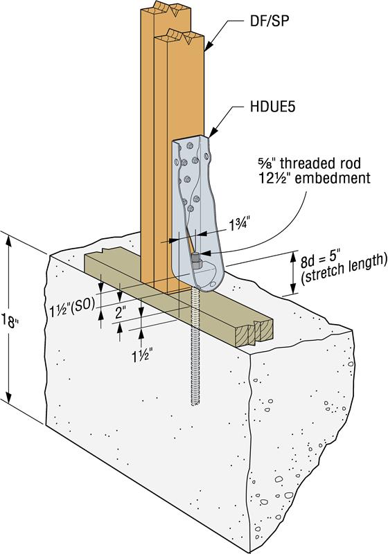
Engineers often provide holdown anchoring solutions near a concrete edge to help prevent overturning of light-frame shear walls during a seismic (or high-wind) event. Sometimes a post-installed anchor must be used if the cast-in-place anchor was mislocated or misinstalled, or is located where a retrofit or addition is needed. Since the cracked-concrete anchorage design provisions went into effect more than a decade ago, it has been challenging for engineers to offer a near-edge post-installed anchoring solution. This is especially true for structures subject to earthquake loads in seismic design category (SDC) C through F. Simpson Strong-Tie’s new SET-3G epoxy is the first anchoring adhesive in the industry to offer exceptionally high bond-strength values that permit ductile anchorage in concrete near an edge. This blog post will cover a specific example that focuses on Chapter 17 of ACI 318-19 to design a threaded rod, anchored with SET-3G adhesive, used to secure a holdown located 1 3/4″ away from a single concrete edge (Figure 1).
Before proceeding with our design example, some background information will be helpful. Section 17.10.5.3 of ACI 318-19 provides four options for designing anchorage in concrete base material. This post will address the two most commonly chosen options for holdown anchorage, (a) and (d). Information on options (b), (c) and more can be found in one of our previous blog posts.
Option (a) requires the anchor system to behave in a ductile manner. To accomplish this, we must meet the following ACI 318-19 requirements:
1) Both the nominal concrete breakout and adhesive bond (pullout) strengths must be great enough by a certain margin to allow a ductile steel insert to exhibit sufficient axial plastic deformation before rupture (17.10.5.3(a)(i)(ii)).
2) The insert must be classified as ductile. A threaded rod conforming to ASTM A193 Gr. B8/B8M (304/316 Stainless Steel) is one example of an insert that meets the ACI 318 requirements to qualify as a ductile steel element (see Ch. 2, definition for steel element, ductile).
3) The insert must have enough stretch length to achieve a meaningful level of axial deformation under tensile loading (17.10.5.3(a)(iii)).
In many cases, engineers have used option (d), which requires that the earthquake force be amplified by an over-strength factor, Ωo. Option (d) makes ductility irrelevant by ensuring that the anchor system behaves in a linear elastic way during an earthquake. For light-frame shear wall construction, Ωo is 3, but it can be reduced to 2.5 for a structure having a flexible diaphragm. Unfortunately, choosing option (d) often results in an amplified earthquake force far greater than the post-installed anchor design strength. This has caused some engineers to resort to expensive solutions such as anchoring through an existing footing into a new reinforced footing underneath.
Anchor Design for Concrete Software Can Help
The free Simpson Strong-Tie Anchor Designer for Concrete software for ACI 318 makes it easy to design a ductile anchor system using SET-3G anchoring adhesive. Figure 2 is a screen shot of our design example. Here is a list of some input information, some of which is shown in the calculation summary and 3D-model tab of the software:
• Strength-level tensile demand load: Nu = 7,600 lb.
• Anchor: 5/8″-diameter ASTM A193 Gr. B8/B8M (304/316 Stainless Steel) threaded rod
• Embedment depth: 12 1/2″
• Single-edge distance: 1 3/4″ (typical for 2×4 stud wall)
• Concrete strength: f’c = 3,000 psi normal-weight concrete
• Cracked concrete
• SDC D
• Hole condition: dry
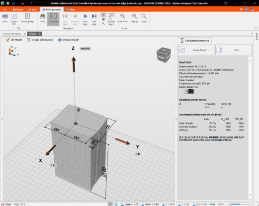
Conveniently, the design strength value for each of the following failure modes — steel, concrete breakout and adhesive bond (pullout) — is summarized on the right. The 3D-model tab shows the anchor located 1 3/4″ away from a single edge with all other edges assumed to be infinite. Note that the adhesive bond (pullout) design strength governs. Before proceeding further, try to answer the following question: Is this anchor system ductile?
To see whether this anchor system is ductile, we first must determine the nominal strength for each failure mode. The nominal strength provides a better representation than the design strength of the relative expected tensile limit of each failure mode. To qualify an anchor system as ductile, section 17.10.5.3(a)(i)(ii) of ACI 318- 19 requires that the following relative strength conditions be met:
1.2 Nsa < Ncb and Na
The nominal steel strength, Nsa, is multiplied by 1.2 to account for the possibility that the ultimate tensile strength of the insert (threaded rod in our case) could be larger than expected. This check is important as it helps to increase the probability that non-ductile failure modes — namely, concrete breakout (Ncb) and adhesive bond (Na) — will not occur. The nominal strength for each failure mode can be calculated backwards from the design strength as follows:
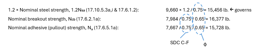
Because the steel failure mode governs (1.2Nsa = 15,456 lb.) and the steel in this design example is ductile (ASTM A193 Gr. B8/B8M (304/316 Stainless Steel)), the anchorage is considered ductile. It’s important to note that the nominal strength does not include the material reduction factor, φ, which is 0.75 for steel and 0.65 for breakout and adhesive bond. It also does not include the 0.75 reduction factor for anchorage located in SDC C – F. This reduction factor accounts for the possibility of increased cracking and spalling in the concrete caused by seismic activity.
Next, the threaded rod must have a stretch length of eight times the nominal diameter of threaded rod (8d) according to 17.10.5.3(a)(iii) — or, in our case, 5″. In our example, the sill plate is 1 1/2″ thick and the distance between the anchor nut and HDUE5 base, SO, is 1 1/2″. SO is published in the Simpson Strong-Tie Wood Construction Connectors catalog. To meet the 8d stretch length, the holdown will need to be raised 5″ – 1 1/2″ – 1 1/2″ = 2″ above the 2x sill plate (Figure 1). If the anchor needs to be extended with a coupler nut to reach the holdown, then the 8d stretch length should (1) only apply where the threaded rod is continuous and (2) never include the length of the coupler nut. Simpson Strong-Tie HDUE holdowns can be raised up to 6″ (2 1/2″ for the DTT1 and 4 1/2″ for the DTT2) above the concrete surface (measured to the holdown nut) without having to consider additional rod elongation.
A nice feature of the Anchor Designer for Concrete software is that it performs the ductility check and conveniently shows the results, highlighting in bold font which failure mode governs (Figure 3). The software will show you whether the anchor system, based on the design information entered by the user, is ductile or not.
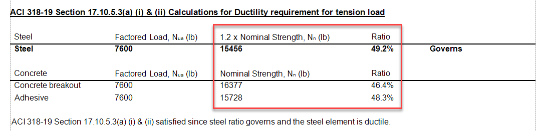
We see that the anchor system, rated for a governing design strength of 7,667 lb. (adhesive bond), can resist the demand load of 7,600 lb. Dead load is not addressed here, but it should be included in the design because it reduces the net uplift force, Nu.

Next, we must choose a holdown. Since ASD values are listed for Simpson Strong-Tie holdowns, we must convert our demand load to an ASD level load. To simplify, we assume 100% seismic loading.
ASD level tensile demand load = 7,600 x 0.7 = 5,320 lb.
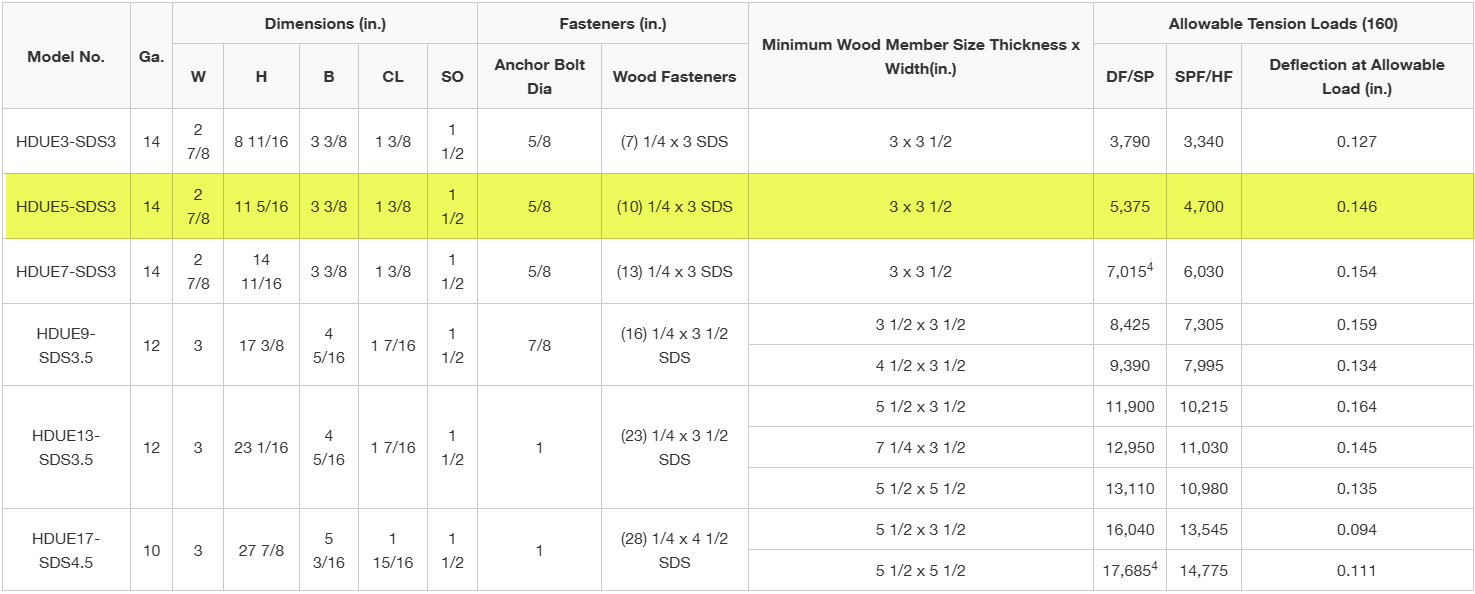
Figure 4 shows a list of predeflected holdowns that can be found in the Simpson Strong-Tie Website. For a DF/SP wood post, we find that the HDUE5 is the best choice. This holdown is rated for 5,375 lb., exceeding the design load of 5,320 lb.
There you have it! A ductile anchor solution near a concrete edge is possible because SET-3G adhesive achieves some of the highest bond-strength values on the market. Ever since the building code started referencing the ACI anchorage design provision more than 10 years ago, engineers have been struggling to make concrete anchorage work for holdowns located near an edge. But now engineers have the option of designing with an adhesive anchor for a more cost-effective solution.
Additional information about Simpson’s newest adhesive, SET-3G, can be found at strongtie.com/SET3G.