


Strengthening of shear walls and diaphragm-to-wall connections has started on Little Tokyo Towers (see photo 1) located in downtown Los Angeles, CA. This senior–living residential facility was built in 1975. Structural analysis by Tuan and Robinson Structural Engineers showed that some modest strengthening was required to improve the building’s lateral system performance in the event of an earthquake.
Author: Jason Oakley
Jason is a California registered professional engineer who graduated from UCSD in 1997 with a degree in structural engineering and earned his MBA from Cal. State Fullerton in 2013. He is a field engineer who teaches specifiers about concrete anchorage and fiber reinforced polymers (FRP) in the S. California and Pacific region. Before joining Simpson Strong-Tie in 2002, he was a design engineer for 5 years working on subterranean parking lots, movie sets, offshore drilling platforms, nuclear power plants, oil refineries, blast-resistant structures, fall protection, dry-dock ship supports and vibration.
Project Snapshot Series Part 2: Historic Theatre Retrofit Using FRP
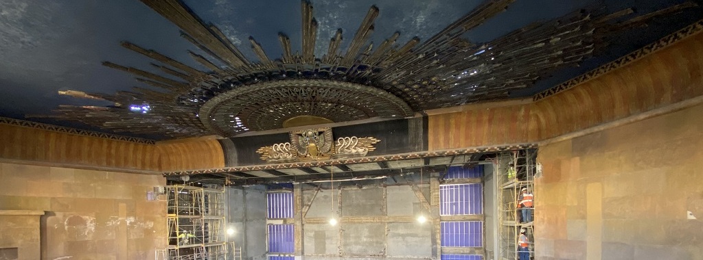
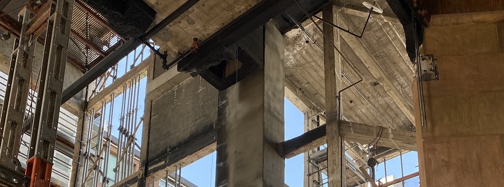
Structural renovation work continues on an historic, 1920s-era theater in Hollywood, California. This major renovation will improve the structural performance of the building and help ensure that theatergoers and building occupants are safe in the event of a major earthquake. We are excited to share a second update on this project that focuses on the use of fiber-reinforced polymer (FRP) for strengthening the theater’s roof diaphragm. Continue Reading
Project Snapshot Series Part 1: Historic Theatre Retrofit Using FRP
Structural renovation work continues on a historic, 1920s-era building in Hollywood, California. This major renovation will improve the structural performance of the building and help ensure that theatregoers and other occupants are safe in the event of a major earthquake.
Project Profile: Reinforcing Concrete Joists to Increase Load Rating
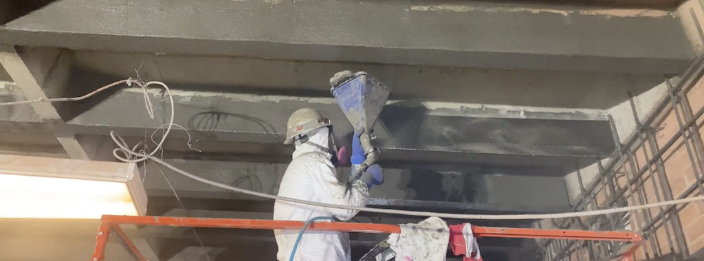
We’re excited to share another fiber-reinforced polymer (FRP) project that required both flexural and shear strengthening (photo below) of reinforced concrete joists to enable the slab floors to carry more live load. The structure is in Southern California, and appears to have been built in the 1950s or 1960s when pan joist construction was common. The EOR for this project, Structural Focus, is an experienced structural engineering firm known for seismic retrofit solutions. The FRP applicator was FD Thomas Structural Specialties, a contractor with decades of FRP installation experience.
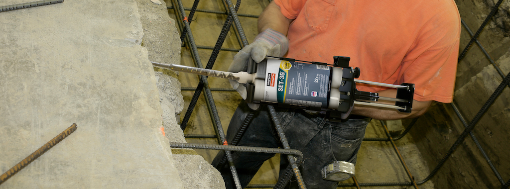
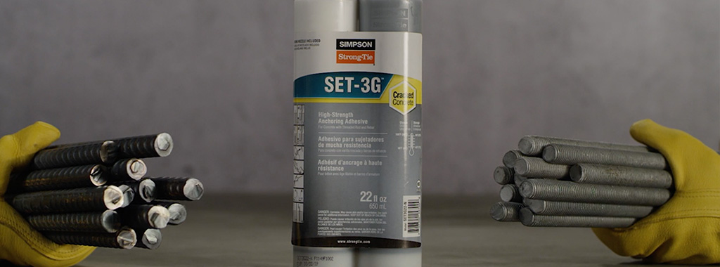
Reasons to Specify SET-3G Adhesive for Anchorage in Concrete Construction
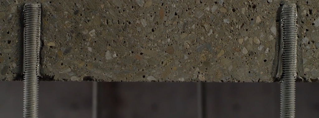
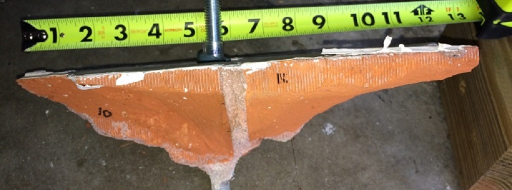
We’ve been receiving a lot of requests lately from engineers wanting to know exactly what the difference is between Simpson Strong-Tie’s relatively new adhesive, SET-3G™, and its predecessor, SET-XP®. Both are epoxy-based adhesives used to anchor threaded rods and reinforcing bars in concrete base material for structural applications. If you perform a live pull test on a ½“-diameter mild steel rod embedded 4“ deep in 3,000 psi uncracked normal-weight concrete, the result will likely be the same; in both cases, the steel rod will break in a ductile manner at around 11 kips. You can see this hourglass-shaped steel failure mode happening in Figure 1. (To learn more about anchorage failure modes and ductility, check out this blog). Yet, the SET-3G design values shown in ESR-4057 come out ahead. But why?
Applying ACI 318-14 Development Length Provisions to Post-Installed Reinforcing Bars Secured to Concrete with Construction Adhesive
The evaluation report, ESR-4057, was recently updated to allow the design of SET-3G adhesive for post-installed reinforcing bars using the ACI 318 development length provision. This blog has been reposted replacing SET-XP with SET-3G using the original design examples. The SET-XP evaluation report, ESR-2508, currently limits f’c to 2,500 psi for seismic applications located in seismic design category C–F. SET-3G does not carry the same limitation allowing for a considerable reduction in development length at higher values of f’c. In general, a substantially lower installation cost can be expected using SET-3G for seismic applications. Additionally, SET-3G has slightly reduced edge and spacing requirements. Engineers can access a free online calculation tool to easily determine the rebar development or lap splice length for either adhesive product.
I first learned about the application of the ACI 318 development length provision to post-installed reinforcing bars back in 2003 when I read Post-Installed Adhesive-Bonded Splices in Bridge Decks, authored by Ronald A. Cook and Scott D. Beesheim. In their series of experiments, holes were drilled adjacent to cast-in-place bars using a carbide-tipped drill bit, and new bars were secured in these holes using an anchoring adhesive presumed to be of a type commonly used in concrete construction.
Continue Reading
Simpson Strong-Tie® SET-3G™ Adhesive Offers a Ductile Solution for Post-Installed Anchorage near a Concrete Edge
Designing post-installed anchorage near a concrete edge is challenging, especially since the ACI provisions for cracked-concrete anchorage went into effect. In the following post, one of our field engineers, Jason Oakley, P.E., explains how SET-3G™ and Anchor Designer™ software from Simpson Strong-Tie make it easier to design a ductile anchor solution.
Engineers often provide holdown anchoring solutions near a concrete edge to help prevent overturning of light-frame shear walls during a seismic (or high-wind) event. Sometimes a post-installed anchor must be used if the cast-in-place anchor was mislocated or misinstalled, or is located where a retrofit or addition is needed. Since the cracked-concrete anchorage design provisions went into effect more than a decade ago, it has been challenging for engineers to offer a near-edge post-installed anchoring solution. This is especially true for structures subject to earthquake loads in seismic design category (SDC) C through F. Simpson Strong-Tie’s new SET-3G epoxy is the first anchoring adhesive in the industry to offer exceptionally high bond-strength values that permit ductile anchorage in concrete near an edge. This blog post will cover a specific example that focuses on Chapter 17 of ACI 318-14 to design a threaded rod, anchored with SET-3G adhesive, used to secure a holdown located 1 3/4″ away from a single concrete edge (Figure 1).
Continue Reading
Understanding and Meeting the ACI 318 – 11 App. D Ductility Requirements – A Design Example
If you’re one of the many engineers still confused by the ACI 318 – 11 Appendix D design provisions, this blog will help explain what’s required to achieve a ductile performing anchorage. Most building codes currently reference ACI 318 – 11 Appendix D as the required provision for designing a wide variety of anchor types that include expansion, undercut, adhesive and cast-in-place anchors in concrete base materials. This blog post will focus on section D.3.3.4.3(a) for an anchor located in a high seismic region. We’ll go over what these requirements are with a simple design example.
Ductility is a benefit in seismic design. A ductile anchor system is one that exhibits a meaningful degree of deformation before failure occurs. However, ductility is distinct from an equally important dimension called strength. Add strength, and a ductile steel element like the one shown in Figure 1 can now exhibit toughness. During a serious earthquake, a structural system with appreciable toughness (i.e., one that possesses both strength and ductility in sufficient degree) can be expected to absorb a tremendous amount of energy as the material plastically deforms and increases the likelihood that an outright failure won’t occur. Any visible deformations could help determine if repair is necessary.

Let’s start off with a simple example that will cover the essential requirements for achieving ductility and applies to any type of structural anchor used in concrete. We’ll arbitrarily choose a post-installed adhesive anchor. This type of anchor is very common in concrete construction and is used for making structural and nonstructural connections that include anchorage of sill plates and holdowns for shear walls, equipment, racks, architectural/mechanical/electrical components and, very frequently, rebar dowels for making section enlargements. We’ll assume the anchor is limited to resisting earthquake loading in tension only and is in seismic design category C – F. Section D.3.3.4.2 requires that if the strength-level earthquake force exceeds 20% of the total factored load, that the anchor be designed in accordance with section D.3.3.4.3 and D.3.3.4.4. We will focus on achieving the ductility option, (a), of D.3.3.4.3.
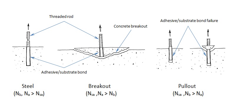
To understand anchor ductility we need to first identify the possible failure modes of an anchor. Figure 2 shows the three types of failure modes we can expect for an adhesive anchor located away from a free edge. These three failure modes generically apply to virtually any type of anchor (expansion, screw, cast-in-place or undercut). Breakout (Nb) and pullout (Na) are not considered ductile failure modes. Breakout failure (Nb) can occur very suddenly and behaves mostly linear elastic and consequently absorbs a relatively small amount of energy. After pullout failure (Na) has been initiated, the load/displacement behavior of the anchor can be unpredictable, and furthermore, no reliable mechanism exists for plastic deformation to take place. So we’re left with steel (Nsa). To achieve ductility, not only does the steel need to be made of a ductile material but the steel must govern out of the three failure modes. Additionally, the anchor system must be designed so that steel failure governs by a comfortable margin. Breakout and pullout can never control while the steel yields and plastically deforms. This is what is meant by meeting the ductility requirements of Appendix D.
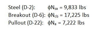
Getting back to our design example, we have a single post-installed 5/8” diameter ASTM F1554 Gr. 36 threaded rod that’s embedded 12” deep, in a dry hole, in a concrete element that has a compressive strength of 2,500 psi. The concrete is 18” thick and we assume that the edge distance is large enough to be irrelevant. For this size anchor, the published characteristic bond strength is 743 psi. Anchor software calculations will produce the following information:
The governing design strength is compared to a demand or load combination that’s defined elsewhere in the code.
Here’s the question: Before proceeding with the remainder of this blog, judging by the design strength values shown above, should we consider this anchorage ductile? Your intuition might tell you that it’s not ductile. Why? Pullout clearly governs (i.e., steel does not). So it might come as a surprise to learn that this adhesive anchor actually is ductile!
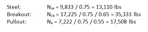
To understand why, we need to look at the nominal strength (not the design strength) of the different anchor failure modes. But first let’s examine the equations used to determine the design strength values above:
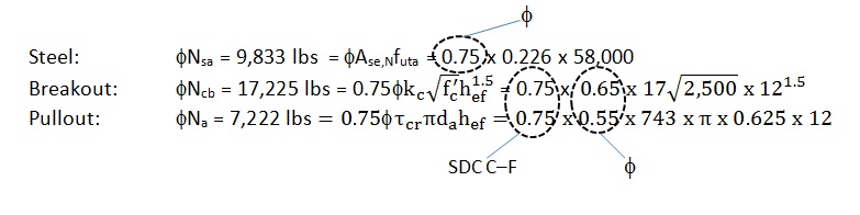
The above values incorporate the notation φ (“phi”) and a mandatory 0.75 reduction factor for nonductile failure modes (Ncb ,Na) for applications located in high seismic areas (seismic design category C–F). The φ factor is defined in section D.4. However, manufacturers will list factors specific to their adhesive based on anchor testing. The mandatory 0.75 reduction comes from section D.3.3.4.4 and is meant to account for any reduction associated with concrete damage during earthquake loading. The important thing to remember is that the nominal strength provides a better representation of the relative capacity of the different failure modes. Remove these reduction factors and we get the following:
Now steel governs since it has the lowest strength. But we’re not done yet. Section D.3.3.4.3.(a).1 of Appendix D requires that the expected steel strength be used in design when checking for ductility. This is done by increasing the specified steel strength by 20%. This is to account for the fact that F1554 Gr. 36 threaded rod, for example, will probably have an ultimate tensile strength greater than the specified 58,000 psi. (Interestingly, the ultimate strength of the ½” threaded rod tested in Figure 1 is roughly 74 ksi, which is about 27% greater than 58,000 psi.) With this in mind, the next step would be to additionally meet section D.3.3.4.3.(a).2 such that the following is met:
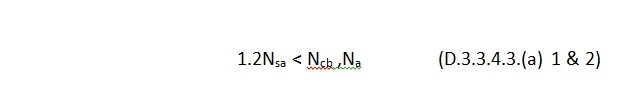
By increasing the steel strength by 20%, the nominal strength of the nonductile failure modes (Ncb ,Na) must be at least that much greater to help ensure that a ductile anchor system can be achieved. The values to compare finally become:
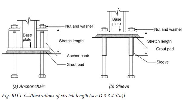
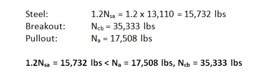 Now steel governs, but one more thing is required. As shown in Figure 3, Section D.3.3.4.3.(a).3 of Appendix D also requires that the rod be made of ductile steel and have a stretch length of at least eight times the insert diameter (8d). Appendix D defines a ductile steel element as exhibiting an elongation of at least 14% and a reduction in area of at least 30%. ASTM F1554 meets this requirement for all three grades of steel (Grade 36, 55 and 105) with the exception of Grade 55 for anchor nominal sizes greater than 2”. Research has shown that a sufficient stretch length helps ensure that an anchor can experience significant yielding and plastic deformation during tensile loading. The threaded rod shown in Figure 1 was tested using a stretch length of 4” (8d). Lastly, section D.3.3.4.3.(a).4 requires that the anchor be engineered to protect against buckling.
Appendix D doesn’t require that an anchor system behave ductilely. Three additional options exist for Designers in section D3.3.4.3. Option (b) allows for the design of an alternate failure mechanism that behaves ductilely. Designing a base plate (or support) that plastically hinges to exhibit ductile performance is one example. Option (c) involves a case where there’s a limit to how much load can be delivered to the anchor. Although option (c) under D.3.3.4.3 falls under the tensile loading section of Appendix D, the best example would apply to anchorage used to secure a wood sill plate or cold-formed steel track. We know from experiments that the wood crushes or the steel yields and locally buckles at a force less than the capacity of the concrete anchorage. Clearly energy is absorbed in the process. The most commonly used option is (d), which amplifies the earthquake load by Ωo. Ωo can be found in ASCE 7 – 10 for both structural and nonstructural components. The value of Ωo is typically taken to be equal to 2.5 (2.0 for storage racks) and is intended to make the anchor system behave linear elastically for the expected design-level earthquake demand.
These same options exist for shear loading cases. However, achieving system ductility through anchor steel is no longer an option for shear loading according to ACI 318 – 11, because the material probably won’t deform appreciably enough to be considered ductile.
While factors such as edge-distance and embedment-depth restrictions make achieving ductility difficult for post-installed anchors, it should come as some consolation that in many cases the Designer can achieve ductile performance for cast-in-place anchors loaded in tension through creative detailing of reinforcing steel (section D.5.2.9) to eliminate breakout as a possible failure mode. This has been explored in some detail in two previous Simpson Strong-Tie blogs titled “Anchor Reinforcement for Concrete Podium Slabs” and “Steel Strong Wall Footings Just Got a Little Slimmer.”
What are your thoughts? Visit the blog and leave a comment!
Part II: Tensile Performance of Simpson Strong-Tie® SET-XP® Adhesive in Reinforced Brick – Test Results
This post is the second of a two-part series on the results of research on anchorage in reinforced brick. The research was done to shed light on what tensile values can be expected for adhesive anchors. In last week’s post, we covered the test set-up. This week, we’re taking a look at our results and findings.Continue Reading
Part I: Tensile Performance of Simpson Strong-Tie® SET-XP Adhesive in Reinforced Brick: Test Set Up

This week’s blog post is written by Jason Oakley. Jason is a California registered professional engineer who graduated from UCSD in 1997 with a degree in Structural Engineering and earned his MBA from Cal State Fullerton in 2013. He is a field engineer for Simpson Strong-Tie who has specialized in anchor systems for more than 12 years. He also covers concrete repair and Fiber-Reinforced Polymer (FRP) systems. His territory includes Southern California, Hawaii and Guam.
This post is Part I of a two-part series. In this post, we’ll cover the test set-up and next week in Part II, we’ll take a look at our results and findings.
More than half a century ago, reinforced brick was a fairly common construction material used in buildings located in Southern California and probably elsewhere in the U.S. Reinforced brick can be found in schools, universities, and office buildings that still stand today. This material should not be confused with unreinforced brick masonry (URM) that is also composed of bricks but is structurally inferior to reinforced brick. Engineers are often called to look at existing reinforced brick structures to recommend retrofit schemes that, for example, might strengthen the out-of-plane wall anchorage between the roof (or floor) and wall to improve building performance during an earthquake. Yet, limited or no information exists on the performance of adhesive anchors in this base material. This series of posts shares the results of research on anchorage in reinforced brick in hopes of shedding light on what tensile values can be expected for adhesive anchors, including any important findings encountered during installation and testing.Continue Reading