

Continuous rod tiedowns are a common way to restrain shearwall overturning in light-frame structures. Anchoring the rod run in a steel beam can be challenging, however, because the holdown typically aligns with the beam’s web and thus cannot pass through the beam. Welding, on the other hand, can cause brittleness and fracture of the rod or coupler at the location of the weld, especially in high-strength steel rods and couplers. An effective alternative also using high-strength rods is provided by the Simpson Strong-Tie® ATS-SBC steel-beam connector, which comes with a steel plate whose flat edges can be fillet welded to the steel beam or embed plate without brittle failure. Scott Fischer, P.E., of Simpson Strong-Tie explains the results of our lab testing in the following post.
My family and I are about two months into a rather extensive and lengthy home remodel project where we’re adding several hundred square feet, renovating our kitchen and bathrooms as well as doing a complete seismic retrofit with new shearwalls and proper end-of-wall anchorage and new holdowns for overturning restraint. My wife and I have had several discussions about the difference between the slab-on-grade and the raised floor portions of our addition and how the framing system comes together when connecting each.
Though all the end-of-wall anchors are embedded in concrete for our project, there are different ways across the construction industry for anchorage to begin and for how the threaded rods transition into the holdowns. On a much larger scale, mid-rise wood-frame construction anchorage starts vary just as they can in single-family, one- and two-story wood-frame construction. When building light-frame structures that are three or more stories tall, though, a continuous rod tiedown system will most often be used as the holdown for the shearwall overturning restraints.
Run Start Details
There are three main run start details that we see for continuous rod systems used in establishing the lateral-force-resisting system connection at the bottom: concrete, wood beams and steel beams. The most common run start consists of the continuous rod system beginning at an elevated concrete slab referred to as a podium deck. In this case, a steel anchor rod is cast-in-place into the concrete for transferring seismic and high-wind uplift loads directly into the concrete. Reinforcing the concrete podium deck at the location of the anchor bolts is highly critical. For additional information on detailing this connection, see our blog post on Anchor Reinforcement for Concrete Podium Slabs.
Where alternative elevated structural systems are used and the ground- or first-floor framing consists of structural columns and beams, the continuous rod run cannot start at the concrete slab. Alternative detailing is necessary to transfer the forces into the beam. In wood beams, a hole is often drilled from top to bottom allowing the continuous rod to pass through it and connect to a steel bearing plate on the underside; see the Simpson Strong-Tie® wood bearing plate series (WBP). For many steel-beam applications, however, this is not feasible as the holdown aligns with the web and a pass-through detail is not an option. Therefore, the rod must connect by some other means to the structural steel beam.
A Recommendation Against Welding Rods or Couplers
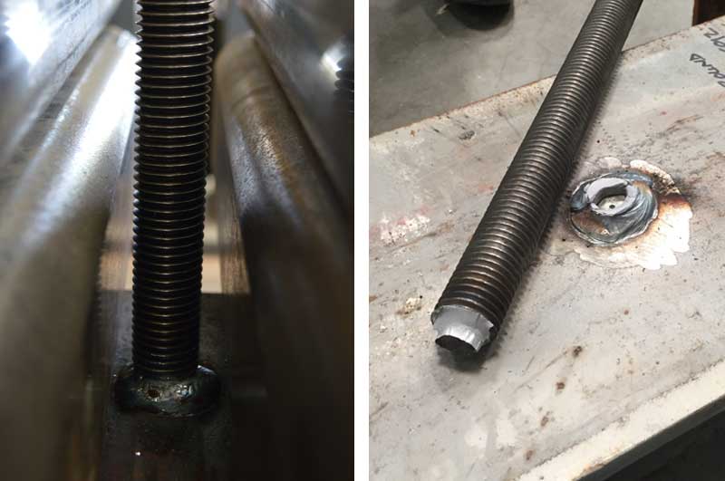
Over the years, we have seen different details to accomplish this connection; for better or worse, two common means are field-welded connections of either the threaded rod or the coupler directly to the steel beam as depicted below.

Being that this connection is the root of your attachment for your entire lateral-force-resisting system, it is crucial to properly transfer the forces. When it comes to welding rods or couplers, I would imagine most of us would want to make certain that all precautions and code requirements are being considered. Simpson Strong-Tie does not recommend the practice of welding threaded rods or couplers to steel beams as a result of recently completed testing performed under several different installation conditions.
Here is a list of considerations:
- Anchoring rods (used for the beginning of a rod-run start) are commonly specified as ASTM A307, A449, and F1554 Grades 36, 55, and 105.
- Though AISC Design Guide 21 on Welded Connections indicates that some of these threaded rods have specs that may be satisfactory for welding, the design guide states that “unless the supplier of the anchor rod can provide assurance that the compositional limits of ASTM A36 have been achieved, weldability of F1554 Grade 36 should be investigated.”
- ASTM A307 material is the only specification that contains supplementary requirements for welding; however, when standard-strength rod is supplied to the job, there is no guarantee that this will be the material provided — adding uncertainty to the acceptability of welding even A307 rod.
- AISC does not recommend welding of high-strength rods with the following specifications: ASTM F1554 Grade 105; A325; A193 Grade B7; A354 Grades BC and BD; or A449.
- Section 4.5.1 of Design Guide 21 specifically prohibits the welding of all quenched and tempered grades.
- The general answer to the question, “Is welding of high-strength bolts allowed?” is “not recommended per AISC” when using the above ASTM specifications.
What is unique about these specs and their association with being ‘high-strength’? In general, high-strength rods are defined as rods made of steel consisting of medium carbon or alloy material which undergoes a heat-treating process to develop the strength properties to meet the requirements of a given specification. This rod steel develops strength and ductility characteristics through controlled quenching (rapid cooling of metal to gain strength) and temper treatments. At the same time, however, this process often increases the brittleness of the steel.
Precise control of time with the application of temperature during the tempering process is critical to achieve an anchor rod with well-balanced mechanical properties. A meticulous blend of art and science occurs during the manufacturing process of these high-strength rods. It is likely, therefore, that the heat and process occurring in an uncontrolled environment, such as in field welding, would alter the physical properties, ductility, and strength of the steel rod. In addition, since high-strength nuts and couplers are generally fabricated from material that exhibits characteristics similar to those of high-strength rods, including a potential for embrittlement, it is also not recommended to weld couplers to steel beams. For previous discussions on this topic, you can read our SE Blog on Welding High-Strength Anchor Rods.
The R&D Testing of High-Strength Rods and Couplers
Now that we know a little more about the process and specifications that go into the manufacturing of high-strength rods, let’s take a glimpse into what we investigated in our R&D testing labs on this topic. During our research, we tested high-strength (A354 Grade BD) and A36 threaded rods welded to an 8″-wide x 10″-deep wide flange section (grade A992) as well as high-strength and standard-strength couplers welded to a similar wide flange beam. A general summary of the test description, average ultimate test loads, and failure modes are shown below in Table 1.
| Test Reference | Rod Dia. | Test Description | Plate | Welded Part Tensile Tests | Target Test Load based on Spec. Rod Tensile Capacity (lbs) | Rod Tensile Mill Cert Calc (lbs) |
|
| Average Ultimate Test (lb) | Failure | ||||||
| A | 1" | HS Welded Rod Only | 1" HS Rod Only | 36,105 | Rod Fracture | 70,686 | 91,303 |
| B | A36 Welded Rod Only | 1" A36 Rod Only | 47,827 | Rod Tensile | 34,165 | 42,706 | |
| C | 1" | HS Welded Coupler & Rod | HSC88 Coupler | 67,910 | Coupler Fracture | 70,686 | 91,303 |
| D | A36 Welded Coupler & Rod | CNW1 | 55,542 | Coupler Fracture | 34,165 | 42,706 | |
| E | 1" HS | ATS-SBC Plate Welded 4 Sides | 3"x3"x1.25" | 96,277 | Rod Tensile | 70,686 | 91,303 |
- High strength rod was A354 Grade BD with a mill cert Fy = 137 ksi and Fu = 155 ksi. Target Test Load based on Fu = 120 ksi.
- Tensile testing of the high strength HSC88 when tested as a coupler only, attained an ultimate load of 84.87 kips.
- Standard strength rod was F1554 Grade 36 with a mill cert Fy = 55 ksi and Fu = 73 ksi. Target Test Load based on Fu = 58 ksi.
- Tensile testing of the standard strength CNW1 when tested as a coupler only, attained an ultimate load of 52 kips.
- Tapped steel plate for the ATS-SBC is ASTM A36 plate steel.
High-Strength Steel Rods and High-Strength Steel Couplers
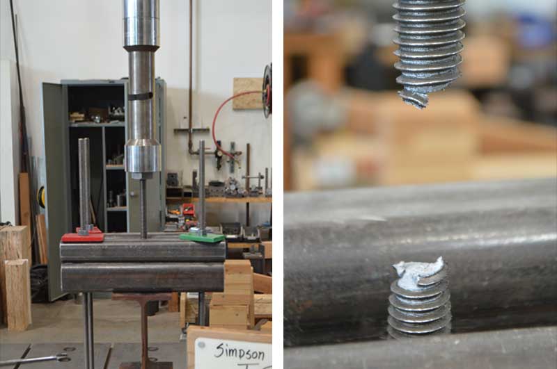
The high-strength threaded rods that we tested were 1″ in diameter. We followed welding specifications as described in the American Welding Society standards, simulating a field-welding process.
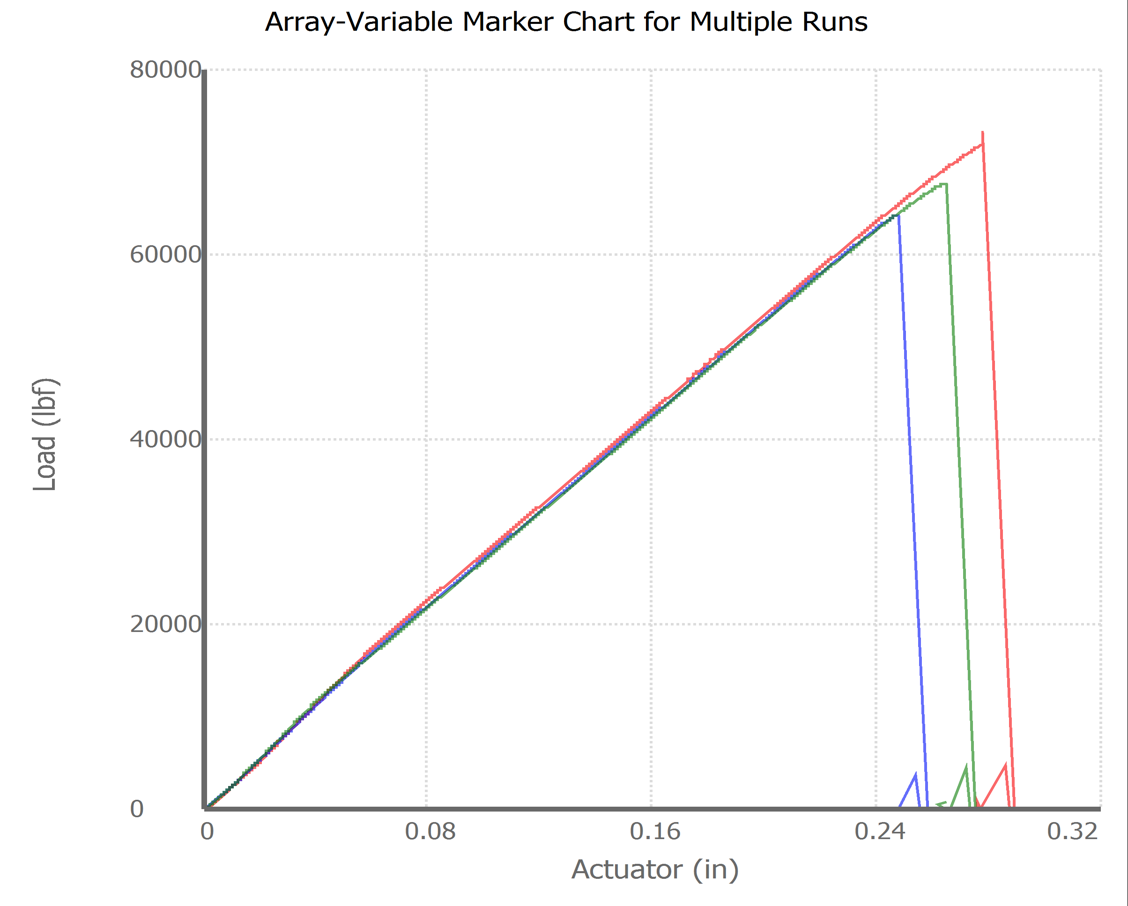
Our target test load was to develop the specified ultimate tensile capacity of the rod. For the case of these high strength rods, the target test load was approximately 71 kips. Our test commenced and the average ultimate load achieved over three tests was only about 36 kips, falling short of the target ultimate by about 50%. Our assessment of failure mode was “Rod Fracture,” as there were no ductile characteristics displayed and the cross section of the steel at the failure location appeared to fracture at the weld.
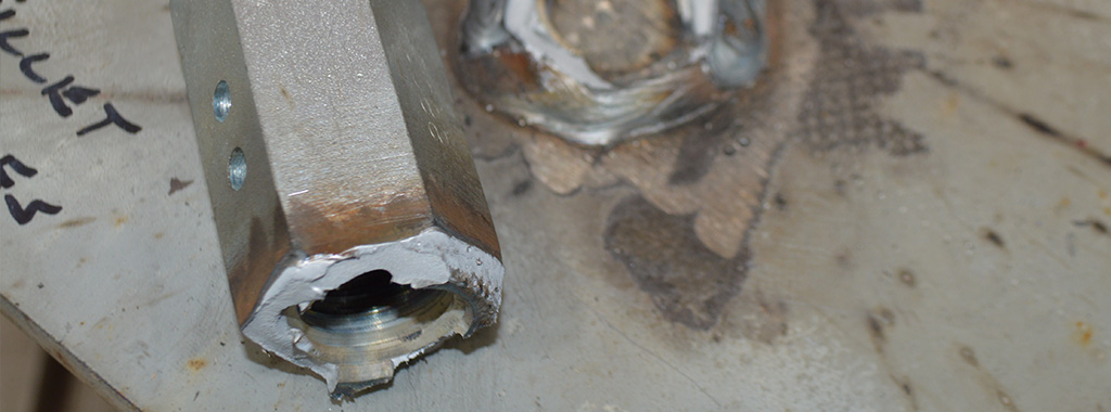
Brittle Failure of Welded HS Threaded Rod
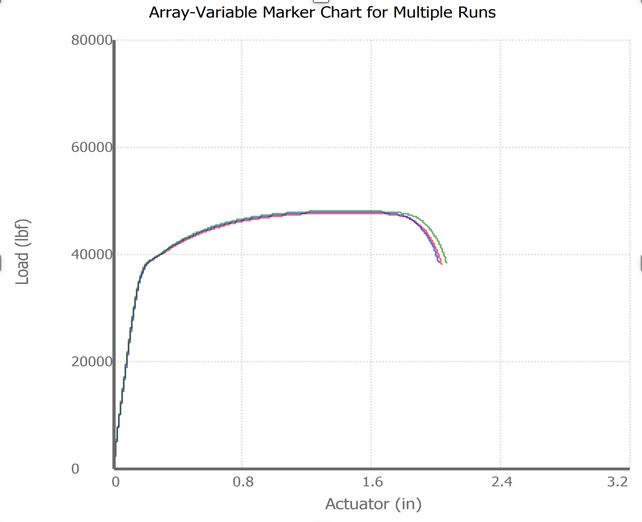
Load Vs Displacement

We then performed a similar test using a high-strength coupler where our target was also to develop the rod tensile capacity. The average ultimate load achieved over those three tests was considerably closer to our target of 71 kips but still fell short, at an average load of about 68 kips. We also performed tension tests of the coupler only where no weld was introduced and we attained an average ultimate test load of around 85 kips. Since neither the rod tensile capacity nor the coupler tensile capacity was attained during the test, there is a high likelihood that the heat during the welding process compromised the integrity of the coupler. In either case, it was a brittle failure and the target was not attained.
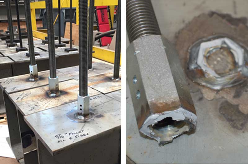
Brittle Failure of Welded HS Coupler
Load Vs Displacement
Standard-Strength Steel Rods and Standard-Strength Steel Couplers
The Grade 36 standard-strength rod that we tested was also 1″ in diameter, and the same American Welding Society standards were used for our field welding.
Similar to the high-strength rod test our target test load was based on the ultimate tensile capacity of the standard strength rod. Using rod material with an ultimate strength of Fu = 58 ksi, the target test load was approximately 34 kips. Our test commenced, and the average ultimate load achieved across three tests was just over 47 kips, where a ductile steel failure was achieved and our target was actually exceeded. An interesting finding is that the A36 welded rod achieved a test load that was 11 kips greater than the welded HS rod (47 kips vs. 36 kips); the HS rod fractured in a brittle manner directly at the weld location, whereas the A36 rod had a ductile tensile failure.
Ductile Failure of Welded Standard Strength Threaded Rod
Load Vs Displacement
We then performed a similar test using a CNW standard-strength coupler where our target was again to develop the rod tensile capacity. The average ultimate load achieved of those three tests did exceed our target of 34 kips; however, the failure was still brittle in that the coupler fractured at the weld location.
Rod-to-Steel-Beam Connector (ATS-SBC)
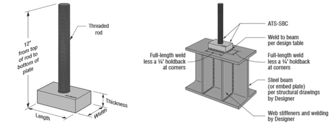
We then tested our new rod-to-steel beam (ATS-SBC) connector. The ATS-SBC is a rectangular steel plate with a tapped center hole that receives the high-strength threaded rod with full thread engagement. For comparision purposes, we tested the product SKU that is designed for a 1″ diameter rod. When it came to the welding standards for the steel-plate-to-beam connection, we followed welding specifications as described in the American Welding Society standards.
This connector features a preattached high-strength steel threaded rod and weldable steel plate where the flat edges are fillet welded to the steel beam or embed plate. The weld length and throat thickness specifications can be found in our F-L-SRS18 design guide.
Also, we recently posted a series of Strong-Rod Systems installation animations, and we included one for the ATS-SBC .
Below are depictions of how the ATS-SBC can be welded to a steel beam. Note, the beam and web stiffeners are per the design structural drawings.

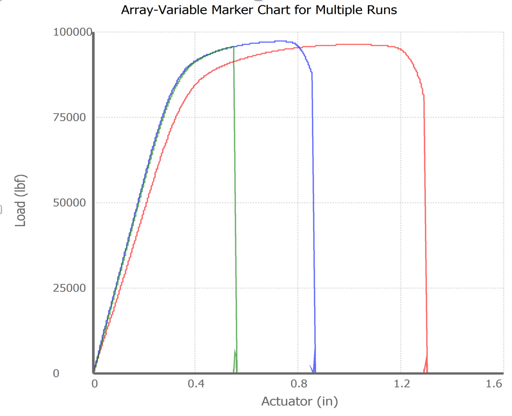
Now back to our testing…. For our comparison study of the ATS-SBC, we welded four sides of the 3″ x 3″ x 1.25″ steel plate to the steel beam and found that 1″ high-strength rod tensile capacity was easily attained with a ductile steel failure in the rod at a little more than 96 kips. Remember, the high-strength rod that was welded directly to the steel beam failed at about 36 kips and the welded high strength coupler failed at around 68 kips — each in a brittle manner.
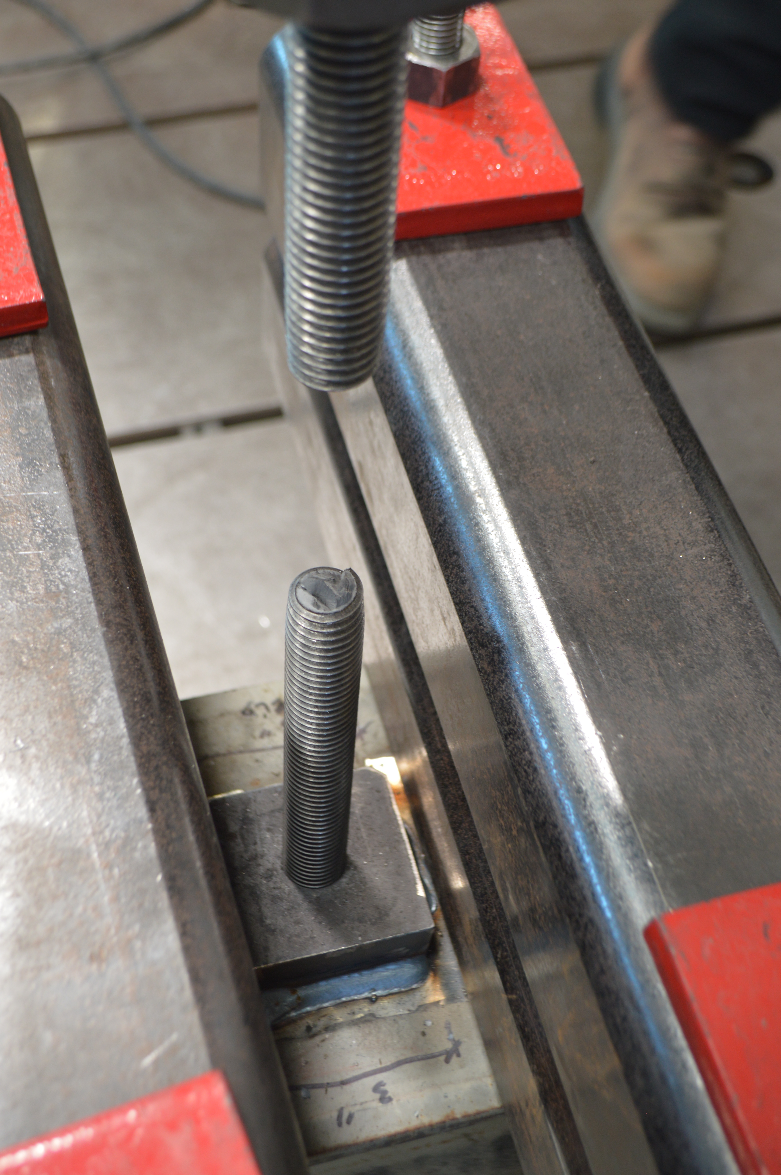
Ductile Failure of the High Strength Threaded Rod of the ATS-SBC
Load Vs Displacement
When determining our published allowable limits for this connector, we calculated the minimum of the following criteria: the allowable tensile capacity of the threaded rod; thread stripping of the rod and the threaded plate; tested value of the ATS-SBC with appropriate safety factor; and calculated weld capacity where the minimum weld length and throat thickness were established to exceed the rod tensile capacity.
In all tests performed, the ATS-SBC (SKUs beginning at ⅝” diameter threaded rod and up to 1½” threaded rod), test failure mode was rod ductile steel tensile failure with the target load being the calculated tensile capacity of the high-strength threaded rod. No brittle steel failures were observed during testing and the potential for embrittlement was eliminated due to the fact that no weld heat ever even approached the threaded rod.
When it comes to connecting your lateral-force-resistant or high-wind restraint system to your foundation, whether it’s a one-story home remodel project or a four- or five-story multi-family project, you need to consider any potential weak links in your continuous load path and ensure they are resolved. Given the art and science associated with manufacturing high-strength rods and all the caution flags that may be raised when welding these rods, we recommend that you consider the alternatives that are available for making this critical run connection in your system.
