Brick or masonry veneer has traditionally posed a problem to homeowners and contractors seeking to attach a deck to a home without removing large portions of the veneer or siding. No longer is that the case, thanks to the innovative BVLZ brick veneer ledger connector from Simpson Strong-Tie. In this post, Rachel Holland, P.E., an R&D structural engineer at Simpson Strong-Tie, explains the research and insights that went into testing and developing this revolutionary connector.
When a homeowner with a brick veneer home wants a deck, how do you safely add outdoor living space? Did you know that the building codes do not allow for the brick veneer to carry any load except for the weight of the brick above it?

Because of these code provisions set forth in the IRC and DCA6, it’s difficult to attach a deck to a structure without either removing large portions of brick, as is required by some products available on the market, or building a freestanding deck. But even a freestanding deck comes with its own set of challenges. Many times the deck posts obstruct downstairs windows and doors. In addition, ensuring the new deck post footing is in undisturbed soil can be challenging. Often, that soil is located much deeper than one would guess, especially if there is a basement, because the soil adjacent to a house is disturbed.
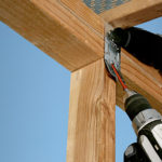
The dilemma of how to safely add a deck to a brick veneer home has been difficult to solve for a long time. After hearing the challenges our customers face, we set out to develop a new solution that would bypass the brick completely and attach the deck safely to the structural framing behind the brick veneer. We spent more than a year researching and designing multiple iterations of various prototypes in order to develop a part that would meet our criteria. From all that trial and error, however, the BVLZ brick veneer ledger connector was born. There are many field variables that made the design of this new product very challenging, but it was that much more rewarding when we were finally able to hit upon the solutions. For example, across the country, existing airspaces between the veneer and the framing vary, brick sizes also vary, and the list of variables goes on. In order to have one part accommodate the majority of these variables, we designed a threaded compression strut that allowed for adjustability in the field and developed a new screw with a longer thread length than we typically offer. There are additional challenges involved with the fact that this connector will attach to, and depend on existing framing. By orienting the screws at an upward angle, we were able to impose a tension force at the top of the rim, and then the compression strut stops the ledger from bearing in on the brick. These two components act in a truss-like manner. Because cross-grain bending is unpredictable, we needed to ensure that the existing framing conditions could support this type of load.
We determined allowable loads for the BVLZ using the lowest of the following values:
- Lowest ultimate load of three tests (or average of six) with a safety factor of three
- Average load at ⅛” deflection
- Calculations per American Wood Council National Design Specification for Wood Construction (NDS)
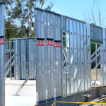
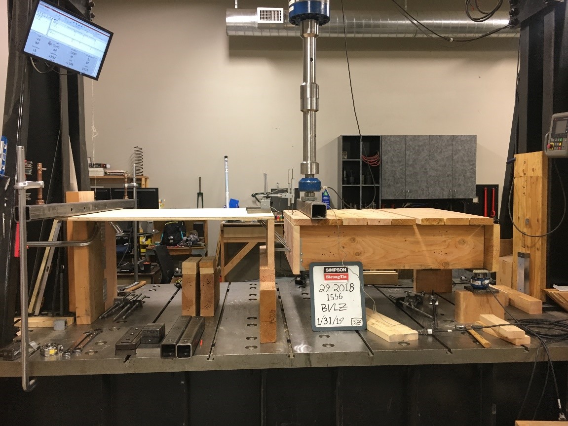
We tested the BVLZ in accordance with AC13 both as a single connection and as a component of a deck system. Here you can see one of the assembly tests with the deck on the right. On the left is an existing interior floor system modeling when floor joists are parallel to the rim board. We discuss testing of wood connectors in more detail in this blog post. For the BVLZ, we evaluated the shear and withdrawal capacity of screws into the rim board with single fastener testing in accordance with AC233.

We calculated the capacity of the Strong-Drive® SD Connector screws for transferring the load from the ledger into the BVLZ connector, and the shear and withdrawal capacity of the Strong-Drive SDWH Timber-Hex screws that transfer the load from the BVLZ ledger plate into the rim board. We also calculated the bearing of the compression strut on a solid rim and wood structural panel (WSP) wall sheathing in front of the rim. The BVLZ is code listed in IAPMO UES ER-280.
From all of the testing and calculations that were performed, we found that the governing load for an engineered design is the bearing capacity of the compression strut on the rim or WSP wall sheathing. In order to maximize the load we needed to increase the diameter of the strut — but again there was a fine balance to uphold, because we wanted to allow the end user to drill reasonably sized holes in the brick veneer. The BVLZ allows the deck to attach to the structure without bearing on the veneer. Through calculations and multiple assembly tests, we confirmed that the strength of the interior framing and fastening was critical to performance. Regardless of how strong we made our part, the framing of the existing building determines the maximum deck load that can be supported by the BVLZ. Therefore, the make-up of the existing structural framing is critical. This connector requires contractors to do some investigative work up front. They need to look into what exists behind the brick. Is there WSP sheathing on the wall? How thick is it? Looking further, where is the rim board of the house? What size is it? What material is it? How is the rim attached to the rest of the framing? Is there interior floor sheathing? How thick is it? How is it attached to the framing? Is there access to the rim from the interior of the home? Answering these questions for each project is essential to understanding whether and how the BVLZ should be used.
Once all the initial work is done, we provide you with the BVLZ allowable downloads so that an engineered design can be completed. If you are following the IRC requirements for deck building, we provide four different prescriptive spacing tables to help you space the BVLZs on your deck ledger.
- Prescriptive spacing table without wood structural panel (WSP) on the wall
- Prescriptive spacing table with wood structural panel (WSP) on the wall
- Prescriptive spacing table with a reinforced rim board and without wood structural panel (WSP) on the wall
- Prescriptive spacing table with a reinforced rim board and wood structural panel (WSP) on the wall
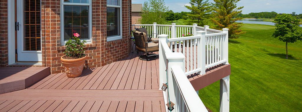
These tables list the maximum on-center spacing for the BVLZ to support different deck spans. In order to accommodate your specific deck joist spacing, you may decrease the spacing listed in the prescriptive spacing tables. The tables require that the existing framing meets the IRC framing requirements. Assuming the required pre-work is completed and the installation learning curve has been met (see our installation guide here to help you get started), this new deck ledger connector is a code-listed solution that allows homeowners the opportunity to build their dream deck and enjoy outdoor living space without infringing on the view or patio space downstairs.
Learn More About the BVLZ in Our Free Webinar

Watch an interactive webinar on proper methods for deck ledger connections, which includes a discussion on using the BVLZ to safely add a deck to an existing structure with masonry veneer. Continuing education units are offered for attending this webinar.