


This is Part 2 of a four-part series I’ll be doing on how connectors, fasteners, anchors and cold-formed steel systems are load rated. Read Part 1 and Part 1A.
These loads just can’t be right! Occasionally, I get this statement from engineers. This happens when they have been specifying commodity fasteners based on NDS load values and they get their first look at our higher screw values. Then the call comes in. They want to talk to someone to confirm what they are seeing is correct. I assure them the loads are right and give them this brief overview of how we got here:
Our first structural screw, the Simpson Strong-Tie(R) Strong-Drive(R) SDS, was originally load rated by plugging the bending yield strength and diameter into the NDS yield limit equations and using the load value from the governing failure mode. As later editions of the NDS modified the calculations and we did more testing, we found that the tested ultimate load of the SDS screw could be as much as ten times greater than the allowable load generated from the NDS equations.
We began working with ICC-ES and AF&PA on a way to analyze screws to determine allowable loads based on tested performance. One of the justifications of generating a new approach is that proprietary fasteners such as the SDS screws have enhanced features and material optimizations that cannot be incorporated into the NDS equations. Ultimately, we came up with a two option approach to solve these issues.
The first option is to use the allowable load from the NDS yield limit equations based on the size and bending yield strength of the proprietary fastener. In addition to the yield limit calculation, the value is verified through testing. The average ultimate load of the verification test divided by 3.2 must be equal to or greater than the calculated value.
The second option is to use an allowable load based on testing alone. The average ultimate load is divided by 5 to determine the allowable load. In both approaches the resulting allowable load can be increased for duration of load per the NDS up to a maximum of 1.6. The full testing and evaluation requirements can be found in ICC-ES Acceptance Criteria for Alternate Dowel Type Threaded Fasteners, AC233.
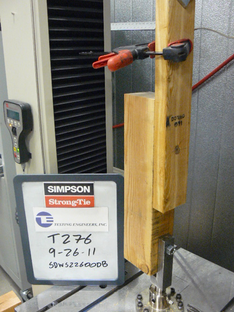
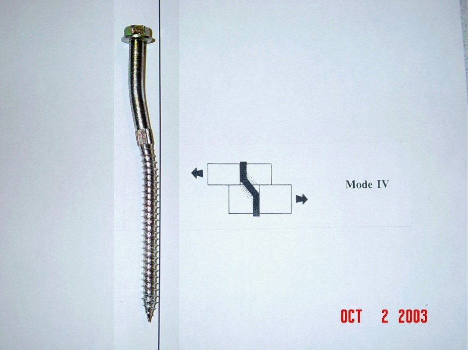
Test programs can be extensive when you consider multiple screw lengths, different side member thicknesses, and wood species. Fortunately, the test assemblies are typically quite simple. As shown in the first photo below, the fastener holds the side member to the main member. Deflection or slip is measured close to the shear plane of the connection and recorded. The yield mode and failure are determined by inspection and recorded. An example of a tested screw is shown in the second photo below.
 By testing actual connection assemblies the full load potential of the fastener can be evaluated. This allows us to bring to market fasteners that are optimized to deliver the highest load while reducing cost and material.
I hope this give a little insight into what is behind the fastener values seen in our load tables. If you have any technical questions, feel free to contact us at strongtie.com/askman.html.
What are your thoughts? Let us know by posting a comment.
– Paul
What are your thoughts? Visit the blog and leave a comment!

Brings up a question that I’ve always had that you might be able to address. Where does the 1.6 max duration limit come from? I’ve often wondered why I can’t use 2 on a handrail for example.
NDS Table 2.3.2 – Frequently Used Load Duration Factors, Cd addresses the different load duration factors. On the Impact Load factor there is a pesky footnote 2, which excludes the use of a load duration higher than 1.6 for for treated wood, and also stipulates that the impact load duration shall not be used for connections.
So if you judge that a handrail load would only be applied for 1 second, it would be permissible to use the impact load duration factor. But the connections would have a maximum load duration factor of 1.6.
Paul, I’m trying to find out why the 2.0 impact factor isn’t allowed for connections, any ideas?