

The evaluation report, ESR-4057, was recently updated to allow the design of SET-3G adhesive for post-installed reinforcing bars using the ACI 318 development length provision. This blog has been reposted replacing SET-XP with SET-3G using the original design examples. The SET-XP evaluation report, ESR-2508, currently limits f’c to 2,500 psi for seismic applications located in seismic design category C–F. SET-3G does not carry the same limitation allowing for a considerable reduction in development length at higher values of f’c. In general, a substantially lower installation cost can be expected using SET-3G for seismic applications. Additionally, SET-3G has slightly reduced edge and spacing requirements. Engineers can access a free online calculation tool to easily determine the rebar development or lap splice length for either adhesive product.
I first learned about the application of the ACI 318 development length provision to post-installed reinforcing bars back in 2003 when I read Post-Installed Adhesive-Bonded Splices in Bridge Decks, authored by Ronald A. Cook and Scott D. Beesheim. In their series of experiments, holes were drilled adjacent to cast-in-place bars using a carbide-tipped drill bit, and new bars were secured in these holes using an anchoring adhesive presumed to be of a type commonly used in concrete construction.
This very informative report is free and available online through the Florida Department of Transportation. Their research showed that post-installed reinforcing bars (PIRBs) behave in structurally similar ways to cast-in-place reinforcing bars. Their contribution, and others, supported the idea that post-installed reinforcing bars could be evaluated using the rebar development length provision (RDLP) of ACI 318 that has been widely used in its current form for many decades. Today, the RDLP can be applied to qualified adhesives as an alternative solution to the anchoring provision of ACI 318. We will look at four design examples using Simpson Strong-Tie® SET-3G® adhesive evaluated in accordance with the RDLP of ACI 318-19, Chapters 25 and 18. The last part of the blog covers some important considerations for using the RDLP.
-
Defining Rebar Development Length
-
Qualification of Post-Installed Reinforcing Bars (PIRBs)
-
Design Examples
a. ACI 318-19, Section 25.4 (development of reinforcement) and Section 25.5 (splices) b. ACI 318-19, Section 18.8 (joints of special moment frames)
c. ACI 318-19, Section 18.10 (special structural walls)
d. ACI 318-19, Section 22.9 (shear friction) -
Closing considerations
1. Defining Rebar Development Length
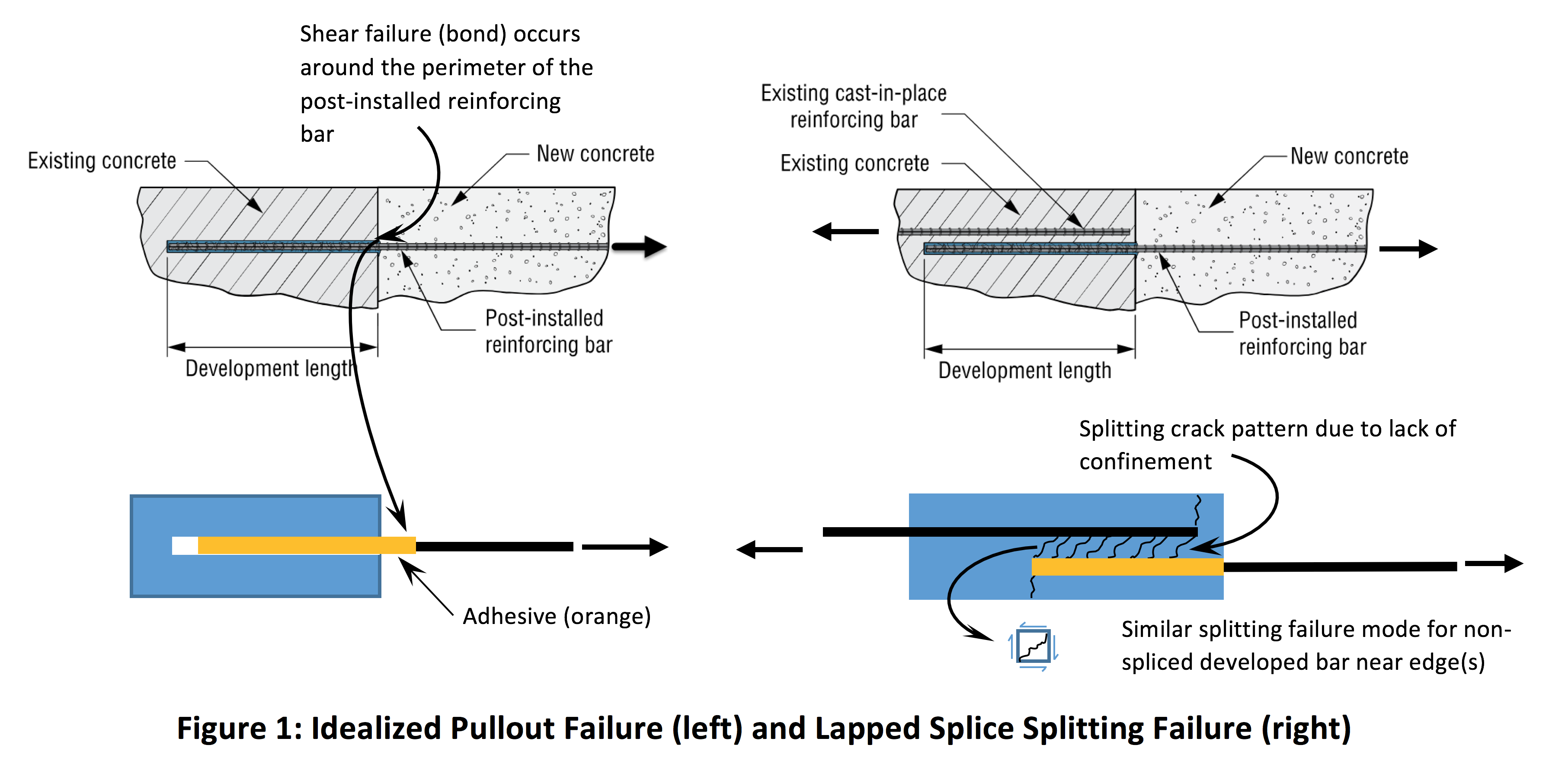
Before we get started, we need to define what it means to develop a reinforcing bar. We also need to differentiate between developing a reinforcing bar for (1) a static (gravity) loading condition and for (2) a seismic loading condition. Considerable ductility would be expected for the latter. Ductility is a measure of how well a material deforms before it ruptures, and the gist of it is covered in a previous blog post. The requirements for each loading condition, static versus seismic, are different. In general, a developed bar that is cast-in-place or post-installed has been embedded deep enough into the concrete to allow the bar to at least reach its yield strength before the concrete splits apart or the bar pulls out of the concrete (Figure 1). Some ductility, or bar yielding, can be expected, and this would be reasonable for a gravity-loaded concrete element. However, seismic connections may require a greater level of ductile response. To increase ductility for seismic use, the reinforcing bar requires a deeper embedment depth. Furthermore, and most importantly, the reinforcing bars must be confined well enough to protect against the brittle-behaving concrete splitting failure mode. A gravity-loaded concrete element is subject to gradual unidirectional loading. In contrast, the reinforcing bars in a seismic connection must withstand load reversals and intensive yielding during a major seismic event.
The RDLP we see today in ACI 318-19 was based mostly on beam tests. Flexure was applied to a reinforced beam causing tension in rebars of a particular development or lapped splice length until failure. Figure 2 shows an example of a lapped splice test subject to a constant bending moment. Seismic Design of Reinforced Concrete Buildings, by Jack Moehle, discusses some of the relevant details of this testing on cast-in-place reinforcing bars and more.

2. Qualification of Post-Installed Reinforcing Bars (PIRBs)
ACI 355.4-11, the qualification standard used to assess post-installed adhesive anchors in concrete, limits the maximum embedment depth to 20 times the anchor diameter. Manufacturers can perform additional testing in accordance with ICC-ES AC308, the acceptance criteria for post-installed adhesive anchors in concrete elements, to significantly increase this embedment depth to permit application of the ACI 318 RDLP to PIRBs embedded up to 60 times the rebar diameter. To be clear, a reinforcing bar anchor is limited to 20 times the rebar diameter and evaluated to Ch. 17 of ACI 318-19. A PIRB is limited to 60 times the rebar diameter and evaluated to Ch. 25 and 18 of ACI 318-19. The most important test requires manufactures to demonstrate similar performance between post-installed and cast-in-place reinforcing bars embedded 35 bar diameters in concrete. Additionally, the adhesive must fall within an acceptable stiffness range. An adhesive that is too stiff may exhibit gradual debonding at the adhesive-concrete interface. This type of failure will begin at the concrete surface, causing gradual unzipping along the bar length as tension is applied. An adhesive that lacks adequate stiffness will probably perform poorly in the sustained load test. Passing the sustained load test means that an adhesive used to secure an anchor in concrete can resist long-term loading. Another consideration is that the gel time of the adhesive must be long enough to allow for a proper installation in a hole that is up to 60 diameters deep. Workers will find injecting a fast-curing adhesive in a deep hole very difficult because it can harden too soon, especially in warm weather, before the installation can be completed.
3. Design Examples
Now let’s look at some design examples to further illustrate the concept of PIRB connections.
a. Design Example 1: ACI 318-19, section 25.4 (development of reinforcement) and Section 25.5 (splices)
Our first example will look at increasing the gravity-load capacity of an existing footing using the Ch. 25 RDLP. Figure 3 shows an exposed footing where excavation has taken place around its perimeter in preparation for a section-enlargement. A “section-enlargement” is a term used to describe the attachment and addition of reinforcement and concrete to strengthen an existing concrete element. In our case, it will serve to increase the gravity-carrying footing capacity by 70% to accommodate the additional weight of a new structure above. Reinforcing bars, used for flexural resistance, are installed around the perimeter of the footing with concrete added after all of the new reinforcement has been set in place.

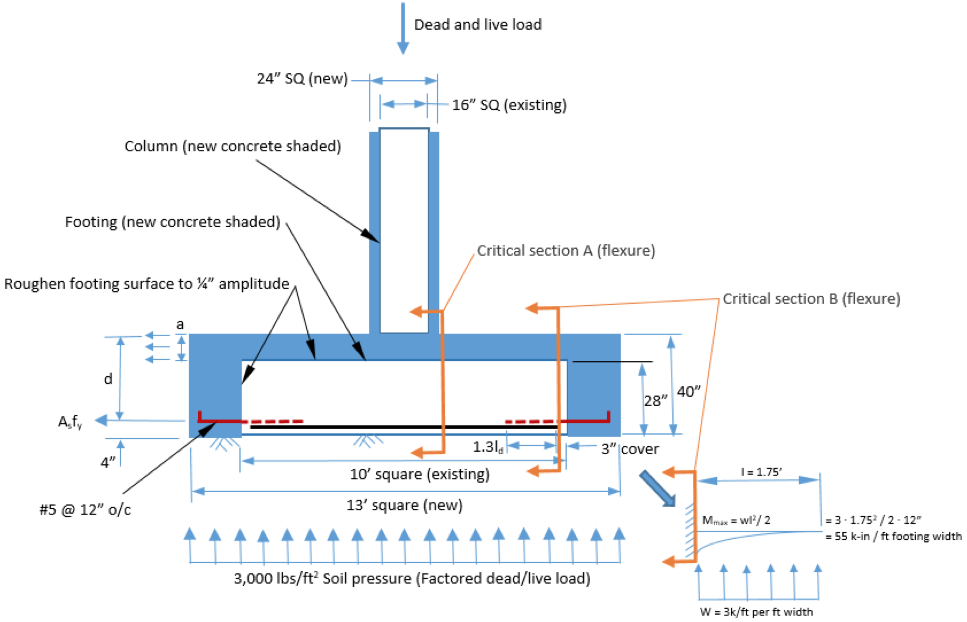
Here are the assumptions for the Figure 3 design example:
- Use Ch. 25 of ACI 318-19 as referenced in ICC-ES ESR-4057, the evaluation report for SET-3G® epoxy anchoring adhesive.
- fʹc = 3,000 psi normal-weight concrete.
- Factored soil pressure of 3,000 lb./ft.2 (dead + live).
- Existing reinforcing bars spaced 12″c. and scanned for location. New PIRB shall be ASTM A615 Gr. 60 #5 rebar spaced 12″ o.c. and meet lap splice spacing requirements of section 25.5.1.3.
- Edge distance of 4″ measured from soil contact to rebar centerline.
- Gravity load only (sustained loading), no seismic.
- 10ʹ square x 28″-thick existing footing increased to 13ʹ square x 40″ thick to accommodate a 70% increase in gravity loading.
- Existing 16″ square column increased to 24″
- Flexural design strength of existing reinforcement at section A (Fig. 3) is sufficient for new loading requirement.
- Temperature and shrinkage reinforcing must be checked separately.
- This example does not address adding reinforcing bars for shear transfer, if required, between the section enlargement and existing concrete.
- In accordance with section 25.4.3.1, the hooked rebar has sufficient development length in the new concrete.
- Assume that load transfer between new and existing rebar is required.
The development length, or embedment depth, of a PIRB is determined using the following equation:

For this design example, edge distance (cb) alone is enough for the confinement term (cb + Ktr)/db to reach the maximum permitted value of 2.5. Letting Ktr, the transverse reinforcing factor, equal zero is conservative. ψt accounts for the weakened bond of the bar due to rising air and water trapped beneath a horizontal bar, but only applies to freshly poured concrete conditions. Both ψt and ψe (epoxy coated rebar factor) equal 1.0. ψs, the bar size factor, equals 0.80 for #5 rebar (smaller bars perform better than larger bars). ψg is the reinforcement grade factor accounting for the yield strength of the reinforcement, ψg equals 1.0 for Grade 60. The straight bar development length calculation is shown below. Simpson Strong-Tie has an online rebar development length calculator that will give the same answer. If (cb + Ktr)/db is less than 2.5, splitting is the likely failure mode. If greater than 2.5, although this term can never be larger than 2.5 for design, this means that pullout (bond) will likely be the controlling failure mode. For this example, the required development length is:

We will evaluate this section enlargement as a lapped splice condition because we are looking to transfer load from the new rebar to the existing rebar. Furthermore, we will (1) treat this as a class B splice (use 1.3 factor) in accordance with section 25.5.2.1 because the bar splices are located along the same edge of the footing and (2) add 3″ to account for the concrete cover leading up to the existing reinforcing bars.

Total embedment depth = 22″ + 3″ (cover) = 25″
Under the RDLP, the nominal strength of a Gr. 60 reinforcing bar is based on yield, or 60 ksi. At 25″ embedment depth, the bar should reach at least yield before the connection fails due to pullout or splitting.
To determine the flexural design strength of a section enlargement requires using the appropriate strength reduction factor, φ. A reduction factor of 0.90 is used for flexure. Comparing the demand load at section B (Fig. 3) to the flexural design strength:


There are some noteworthy RDLP restrictions in ACI 318-19. While section 25.4.10.1 does permit a reduced development length for excess reinforcement, section 25.5.1.4 does not allow this for a lapped splice. Furthermore, section 25.5.2.2 requires the larger of the spliced bars to determine the development length. A much larger-diameter cast-in-place bar will require an exceptionally deep embedment depth for a smaller diameter PIRB resulting in an impractical solution for an application like this. Because the demand-to-capacity (DCR) ratio is so low, less than 10%, would it be reasonable to evaluate this design example using the non-lapped splice condition? This would certainly give the engineer greater design flexibility and result in a more practical solution that is arguably still safe.
b. Design Example 2: ACI 318-19, section 18.8 (joints of special moment frames)
Our second design example will look at adding a new beam to the outside of an existing special moment frame as shown in Figure 4. This could be for a seismic retrofit or for a building expansion in a high-seismic region.
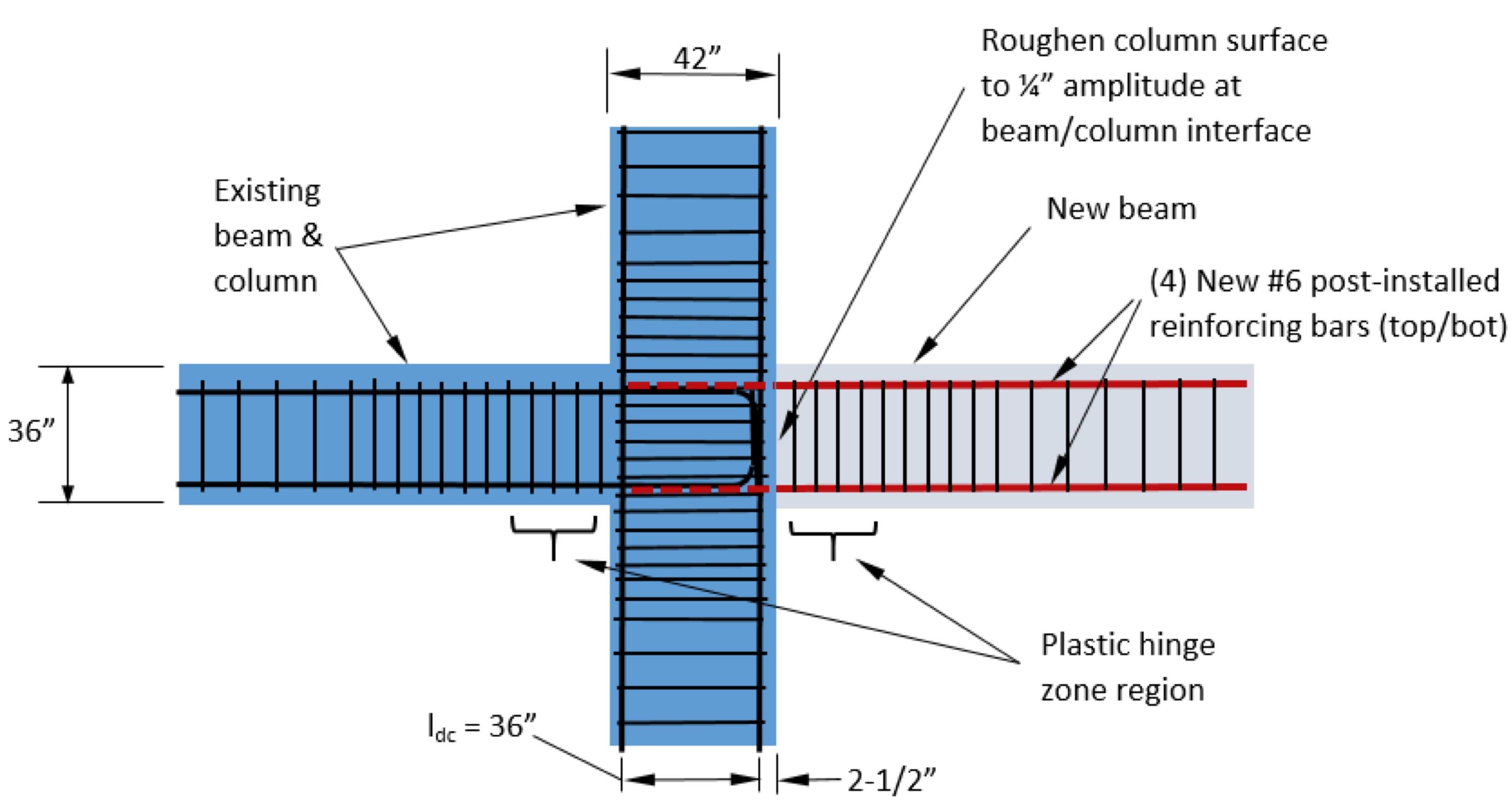
Here are the assumptions for the Figure 4 design example:
- Use Ch. 18 of ACI 318-19 as referenced in ICC-ES ESR-4057 for SET-3G® epoxy anchoring adhesive.
- f’c= 4,000 psi normal weight concrete.
- (4) Gr. 60 #6 rebar conforming to ASTM A615 top and bottom @ 4″ horizontal spacing.
- This design complies with the strong column (weak beam) requirement of section 18.7.3.2.
- The new reinforcing bars do not fall within the plastic hinge zone of the existing beam and therefore the performance of the existing beam, as originally designed, remains unchanged.
- Column provides sufficient confinement for new PIRBs to prevent splitting.
Section 18.8.2.2 requires that the development length be determined in accordance with 18.8.5. Keep in mind that core samples may show a higher concrete compressive strength (f’c) than shown in the structural drawings allowing for a reduction in the required development length. We start by using the hook development equation found in section 18.8.5.1.
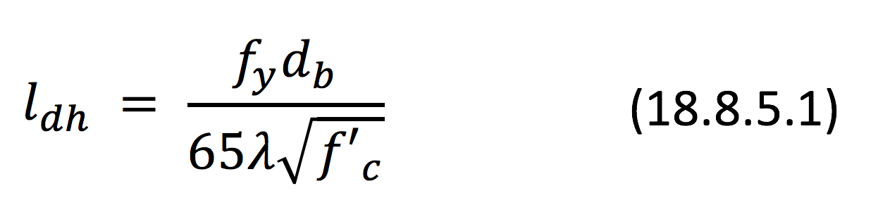
While this equation does account for reverse loading during a seismic event, it also assumes that the moment frame joint is confined to prevent the non-ductile splitting failure mode. Transverse reinforcing is one way to accomplish confinement. We apply part (a) of section 18.8.5.3 to convert the hook development length to a straight bar development length and let λ equal one for normal-weight concrete.
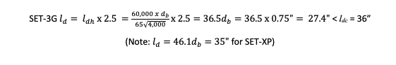
Section 18.8.5.4 requires that any portion of the development length, ld, that falls outside the confined core, ldc, must be increased by 60% because the portion of the bar located outside a confined region may experience higher bond and splitting stresses. Fortunately, ld in this example will fall within the confined region of the column. If the development length had extended through the column too far, then its impact on the performance of the existing plastic hinge would need to be evaluated. The total length, measured from the edge of the column, is as follows:

At this embedment depth, the PIRBs will add strength and make a ductile performance contribution to the building’s lateral system. Each #6 bar can reach a design strength value that is based on bar yield, undergo considerable axial deformation, and withstand load reversals expected in a special moment frame. Ductile behavior is a critical requirement especially for a special moment frame. Allowing the longitudinal beam bars to reach significant post-yield elongation means the special moment frame connection can absorb greater earthquake energy.
c. Design Example 3: ACI 318-19, section 18.10 (special structural walls)
Our third example, shown in Figure 5, will look at developing a post-installed reinforcing bar for a shear wall (“shearwall” in what follows) located in a high seismic region to make up for one cast-in-place bar that was inadvertently left out of the mat foundation prior to the concrete pour. This reinforcing bar will become a part of a sufficiently confined boundary element of a shearwall where yielding of the longitudinal bars is expected during a major earthquake event. The mat foundation is very thick and covers a very large area.
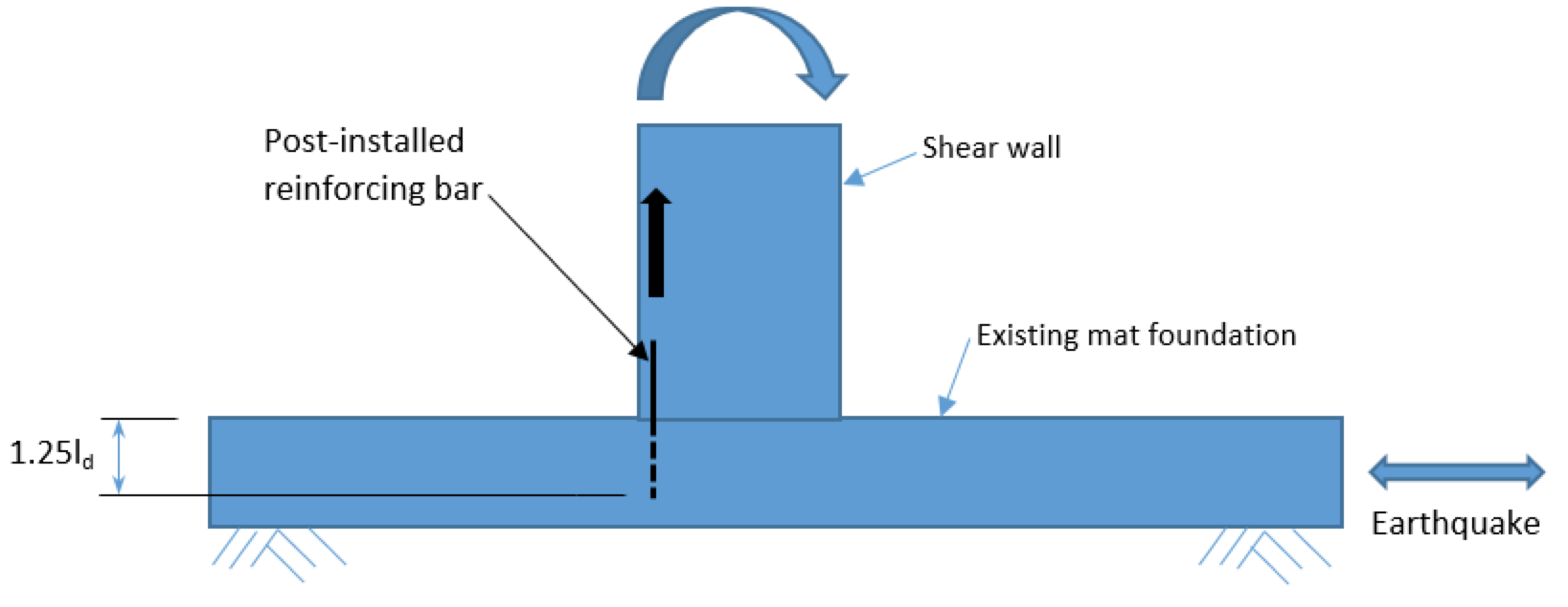
Here are the assumptions for the Figure 5 design example:
- Use Ch. 18 of ACI 318-19 as referenced in ICC-ES ESR-4057 for SET-3G® epoxy anchoring adhesive.
- f’c=4,000 psi normal-weight concrete.
- (1) Gr. 60 #8 rebar conforming to ASTM A615.
- Connection is far away from any edge and therefore considered confined.
If we assume bar yielding, section 18.10.2.3(b) requires increasing the development length of the longitudinal reinforcement by 25% in case the actual yield strength exceeds the specified yield strength of the bar. By inspection, the term (cb + Ktr)/db = 2.5. From Eq. (25.4.2.4a), including the 25% increase, we get:

Note that 35.6db is similar to the design example 2 result, 36.5db. At 36″ embedment depth, a #8 bar in an extremely confined concrete element is expected to exhibit ductile behavior during a significant earthquake event.
d. Design Example 4: ACI 318-19, section 22.9 (shear friction)
Our last design example will look at using reinforcing bars for transferring earthquake-induced shear forces from a concrete wall to a concrete diaphragm as shown in Figure 6. In this example, several #5 cast-in-place reinforcing bars were mistakenly left out of a new shearwall during construction. The original design called for rebar to be spaced 18″ on center. The objective is to replicate the original design shear strength of 14 kips per bar.
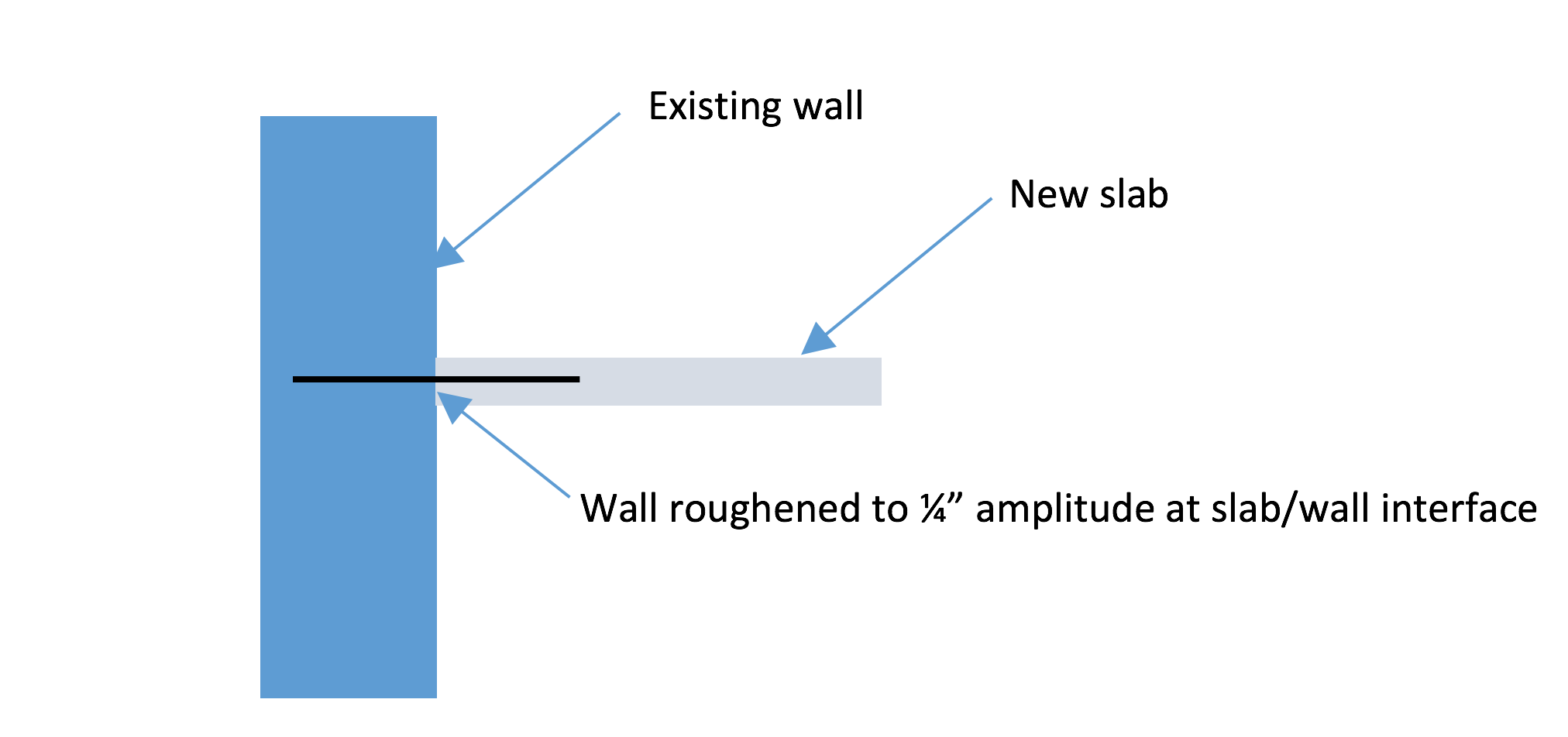
Diaphragms are covered under Chapter 12 of ACI 318-19. Section 12.5.3.7, part (a), permits using the shear friction provision in section 22.9 of ACI 318-19. Section 22.9.5.1 of ACI 318-19 requires that the reinforcing bar can reach yield on each side of the shear plane following the RDLP of Ch. 25.
Here are the assumptions for the Figure 6 design example:
- Use Ch. 25 of ACI 318-19 as referenced in ICC-ES ESR-4057 for SET-3G® epoxy anchoring adhesive.
- #5 rebar conforming to ASTM A615 Gr. 60.
- f’c=4,000 psi normal-weight concrete.
- No edge conditions need to be considered.
- Requirements of ACI 318-19, Table 22.9.4.4 met in the original design.
Using Eq. (25.4.2.4a), the development length is as follows:

The design shear strength for one #5 PIRB is calculated using the following equation:
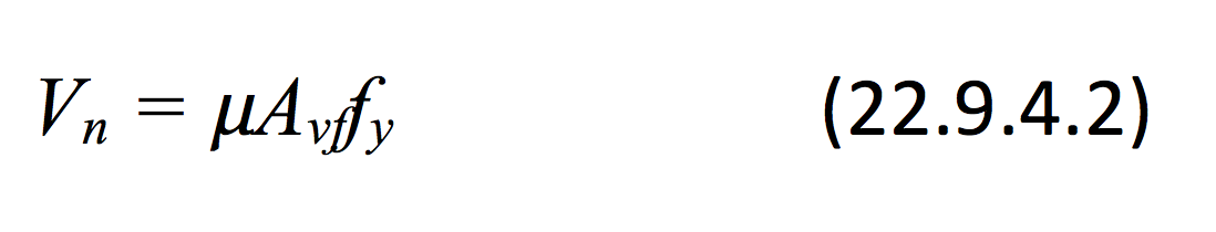
Assuming a surface roughness of ¼” amplitude, µ = 1.0, and the design strength is the following:

A cast-in-place developed bar allows for noteworthy ductile behavior at the interface of two pours for a mostly shear-loaded condition. This behavior is supported by experiments performed by Park and Paulay and presented in Moehle’s book referenced above. We would expect similar behavior for a PIRB following the same provision.
Closing Considerations
The ACI 318 RDLP is now a code-compliant option for engineers looking to apply the same principles to a PIRB using a qualified adhesive. While this provision requires a considerable embedment depth, it offers a solution based on the yield strength of the PIRB. This greatly simplifies design. A seismic application will, unless designed to remain elastic, invariably require that a PIRB can undergo significant yielding. In that case, confinement must be sufficient to permit ductile performance. The RDLP offers a wide range of solutions for various structural concrete applications. However, the designer should consider the following when applying the RDLP to PIRBs:
- The existing concrete may not have sufficient confinement to allow a seismic connection where ductile performance is a requirement. This could mean designing the connection to remain elastic or somehow confining it using a reinforced concrete section-enlargement approach.
- Is there enough physical room to drill a deep hole in the concrete base material? Looking at Figure 3, the trench must be wide enough to permit both the drill length and drilling tool.
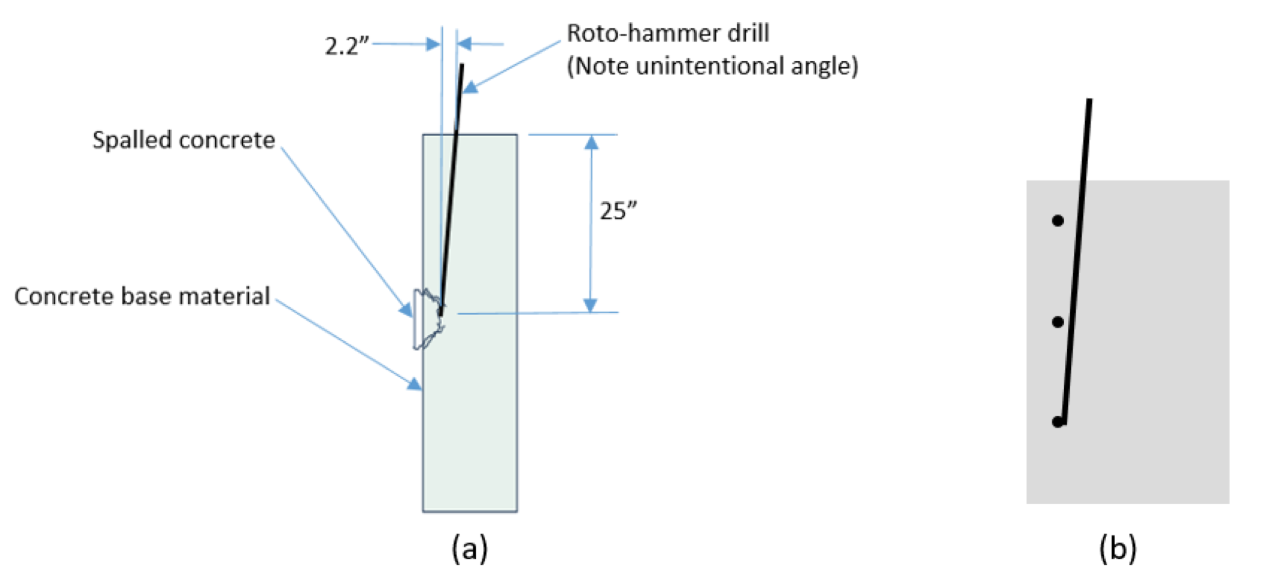
- Are the PIRBs too close to a concrete edge? The edge and spacing requirements of the ACI 318 RDLP are relatively easy to implement for a cast-in-place reinforcing bar. Because drilling holes plumb can be difficult, though not impossible, the risk of spalling the concrete increases if the drill bit tip is inadvertently angled towards the edge of the concrete as shown in Figure 7. If, for example, the required hole depth is 25″ and the drill angle is 5° from plumb, then the tip of the drill would wander away horizontally by as much as 2.2″ towards the edge, potentially resulting in spalled concrete or hitting a cast-in-place rebar. The take away is that engineers should specify bars as far away from an edge as possible when using the RDLP. Alternatively, drill holes with great care.
4. Does the construction crew have the means to drill a deep hole? Most holes are drilled using a rotary hammer drill. With some exceptions, the embedment depth limit for a carbide-tipped drill bit is around 30″. Beyond 30″, typically using a rock-drill or a core-drill becomes a more practical solution.
5. At such extensive embedment depth, how many cast-in-place rebars might be hit? Is it okay to core-drill through existing rebar? Expect much greater embedment depths if the PIRBs must comply with the requirements of section 18.8.5 for special moment frames. Scanning for existing reinforcing bars will help, but this has limitations too.
6. Does enough concrete thickness exist to accommodate an embedment depth based on the RDLP?
7. For great embedment depths, an appropriate adhesive delivery system should be used. One solution uses a piston plug attached to a flexible tube as shown in Figure 8. As the adhesive is injected into the hole, the pressure forces the plug and tube assembly to move out of the hole helping to ensure a void-free installation. This video shows how this system works. Eliminating air pockets maximizes the bond area between the rebar and concrete.

8. In general, ACI 318-19 section 18.6.3.3 prohibits lapped splices in regions that will undergo significant flexural yielding during earthquake loading. However, Moehle’s book does explain some studies done by Paulay et al., Sivakumar et al., and others, who looked at lapped splice performance subject to cyclic loading that considered transverse reinforcement spacing and stress limits, including splice length. Recommendations and insights can also be found in ACI 408.2R-12 – Report on Bond of Steel Reinforcing Bars under Cyclic Loads.
