Many of you reading this may already be familiar with our Strong-Wall site-built portal frame system, or PFS for short. Simpson Strong-Tie launched the PFS last spring to provide designers, builders and contractors in prescriptive markets with a simple and cost-effective solution to meet code-prescribed wall bracing requirements for narrow wall widths.
What you may not know, however, is that for the past year we’ve been diligently working to obtain code coverage for the PFS. So, without further ado, we’re pleased to present the code-listed Strong-Wall site-built portal frame system, which is detailed in ICC-ES ESR-4455.
But before we get into code report specifics, let’s first take a look under the hood and consider what obtaining code coverage entailed in this case. First, we know that the International Residential Code® (IRC®) provides a number of intermittent and continuously sheathed wall bracing methods. Each of these methods may be used in most applications. However, there may be cases where the site-specific conditions are beyond the scope of the IRC, or there just isn’t enough available full-height wall space to accommodate the required wall bracing length. As discussed in an earlier blog post, there are additional wall bracing options available when we need to maintain narrow wall widths so as to maximize openings. Until recently, we’d recommend using a prefabricated Strong-Wall shearwall, and in many cases this is still the best approach. However, when the full strength and stiffness provided by the high-capacity prefabricated shearwall solution is not required, we’re now able to consider the more cost-effective site-builtportal frame system. The important distinction to note here is prefabricated vs. site-built. Our prefabricated Strong-Wall shearwalls are manufactured in a controlled production environment with strict quality assurance measures. There are also existing acceptance criteria (ACs) for prefabricated wood and steel shearwalls that tell us how to test and evaluate the shearwalls so we ensure performance compatible with code-based methods.
When we launched the PFS over a year ago, there were no such acceptance criteria available for proprietary site-assembled wood portal frames that would ensure performance equivalent to existing code-based prescriptive bracing methods. This is where our post PFS-launch journey began. First, it’s important to note that developing a new acceptance criterion is truly a group effort. We worked with a number of partners in the wood industry through an exhaustive process that involved public hearings and multiple opportunities for public comment to shape the AC before it was published. But even before the public process began, we spent months developing and refining the AC with input from our industry partners to ensure that every detail was thoroughly considered. First and foremost, this included determining the appropriate code-based bracing methods for comparison to ensure code-compliance for a variety of loading types and applications. It also included everything from consideration for variable lumber types and conditions that are typical in the field, to allowable field-drilled holes, and everything in between. When the dust settled, we had a robust and well-written document that not only had the Simpson Strong-Tie stamp of approval, but also had broad agreement from the wood industry at large.
View or download a copy of the code report here.
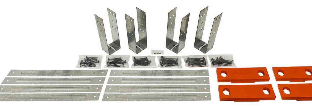
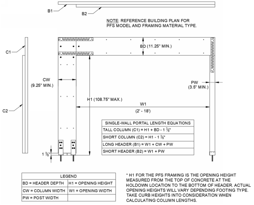
Now that we have some of the background, let’s return to the PFS code report. For starters, we should mention that the PFS is compliant with every edition of the International Residential Code from 2009 through 2018. As in all our code or evaluation reports, we provide a detailed description of the product itself and all components used. In this case, we describe the kit of parts, which includes the PFS holdown, portal straps, post and column bases, and the fasteners required to connect everything together. We also define the applicable lumber types and combinations thereof that are used to construct the nominal 10”- and 12”-wide column members that compose the PFS portal frame. Moving on to design and installation information, the first key piece of information to bring to the forefront is that the PFS may now be specified in Seismic Design Categories D0-D2, but with one caveat: For these cases, PFS use is limited to single-story applications.
Another important bit of design information is the basis for the minimum total length of braced wall panels for a wall line containing the PFS. This required bracing length, which is defined in Table R602.10.3 of the 2018 IRC, shall be taken as the same value as is used for the bracing Method Portal Frame with Holdowns (PFH). On the capacity side of the equation, the maximum contributing length of bracing for both methods is equal to 4 ft. for a single-wall portal and 8 ft. for a double-wall portal; a full summary of PFS bracing lengths for all combinations of framing materials and loading conditions is shown in Table 4 of the code report. The acceptable mixing of braced wall panel methods for wall lines containing the PFS shall also be the same as for Method PFH.
Header selection is another topic in the evaluation report that warrants some discussion. Just as they are for the required bracing length and for mixing rules, the PFS and Method PFH are remarkably similar with respect to header criteria. Both bracing methods require a minimum nominal 12” deep header member and allow for header span lengths ranging from 2 ft. to 18 ft. in order to achieve the required portal system performance. However, for cases where large gravity loads are present, the allowable header span may be limited unless the header depth is increased. There are a number of resources available to aid designers in header selection, including the prescriptive span tables in the IRC and those from respective LVL manufacturers.
Now for a bit of the fine print. Of course, the maximum contributing bracing lengths listed in Table 4 of the evaluation report must not be exceeded. We also need to ensure that the lumber material used to construct the PFS is in decent condition. This means that we’re not permitting end checks or splits in the connection zone near the holdown, and field holes are limited to the regions shown in Figure 10 of the code report. Further, the PFS components and lumber must be protected from weather exposure prior to and during installation. And one more thing that isn’t permitted, or I should say required — there are no special inspection requirements!
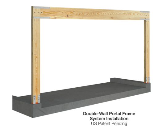
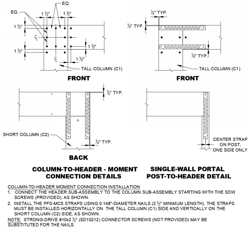
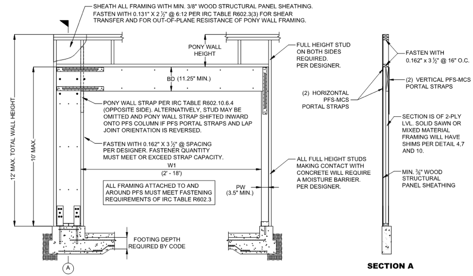
Lastly, all construction details addressing hardware installation, the header-to-column connection, pony wall assembly, built-up members, and member shimming are provided in the installation details, some of which are shown in what follows. In short, ICC-ES ESR-4455 contains all the necessary and relevant information that a designer needs to specify the PFS, that a builder needs to install the PFS, and that a building official needs to approve its use.
For a postscript, we should also mention that our Strong-Wall® Bracing Selector (SWBS) has just been updated with the latest and greatest solutions for our site-built Strong-Wall portal frame system. These updates include the new seismic solutions for the PFS, wall bracing solutions for installations on CMU stemwalls, and cast-in-place anchorage solutions to complement the existing post-installed anchorage solutions. Prescriptive bracing designers may also recall the benefit of using the selector in conjunction with the Wall-Bracing-Length Calculator (WBLC). To refresh your memory, when designers start with the WBLC to determine required wall bracing lengths for up to seven parallel wall lines, they can export those bracing lengths as well as project and jobsite information directly to the SWBS with the click of a button. The SWBS will then provide a list of Strong-Wall panels that provide an equivalent bracing length, evaluate their anchorage requirements, and return a list of pre-engineered anchor solutions for a variety of foundation types.
Please feel free to take a minute and check out these tools and resources to see whether the code-listed Strong-Wall® site-built portal frame system may be the right solution for your next prescriptive wall bracing project.