

After years of development, we’re excited to introduce the newest member of the Strong-Wall® shearwall family – the Strong-Wall high-strength wood shearwall (WSWH).
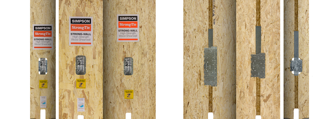
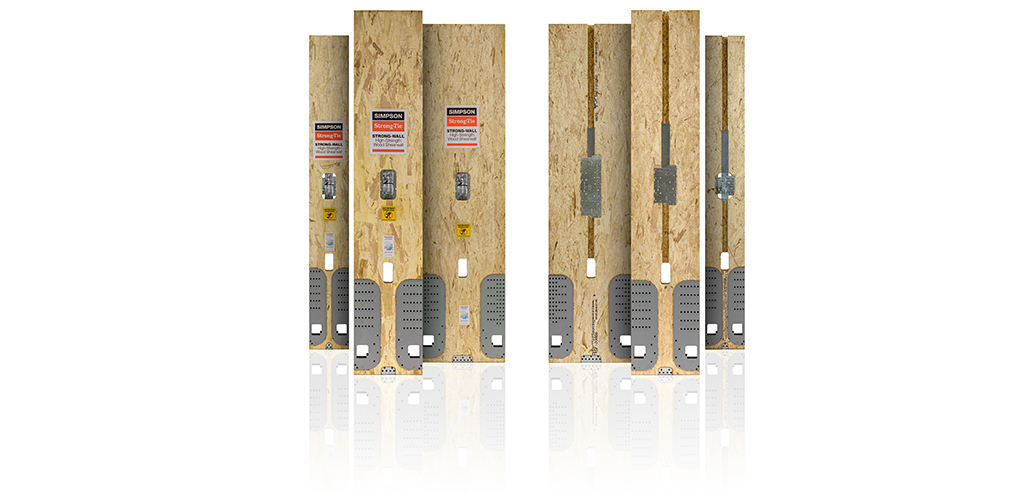
The Strong-Wall High-Strength Wood Shearwall Lineup
The WSWH is a high-strength prefabricated shearwall composed of a custom-routed laminated strand lumber (LSL) body and proprietary steel holdowns. The shearwall is remarkably versatile in that it can be field-trimmed to accommodate any number of framed wall heights and rake walls with roof pitches up to 45º. The WSWH will further accommodate field-drilled holes, both large and small, in designated areas of the edge and face of the panel.
At this point, you may have noticed that this new shearwall sounds a lot like our old wood shearwall. You’re right, there are a lot of similarities between the Strong-Wall wood shearwall (WSW) and the WSWH. They both feature the same fundamental panel assembly makeup and field-trimmable features described above. They’re both available in the same three model widths with the same on-center anchor bolt spacing. And they’re both code approved and included in the same evaluation report, ICC-ES ESR-2652. So what’s different about this new wall? Well, quite a bit, actually.
Before we get into the details of the WSWH, I’d like to introduce a notable design principle:
“Design is not just what it looks like and feels like. Design is how it works.” — Steve Jobs
In the case of a prefabricated shearwall destined to spend 99.9% of its life enclosed within the wall cavity of a structure, it’s a natural inclination to agree that look and feel are much less significant. While I’m actually a fan of the aesthetics of the Strong-Wall high-strength wood shearwall, I’m much more excited about how it works.
I’ll start out by acknowledging that all high aspect ratio prefabricated shearwalls are evaluated to the same test criteria — which levels the playing field in the industry. The allowable wind and seismic shear loads are determined based on the lesser of the strength-based and drift-based limits, and there are additional performance requirements instituted for higher seismic design categories to ensure compatibility with code-based methods. I go into quite a bit more detail on the topic of evaluating prefabricated shearwalls in an earlier blog post. So the test criteria establish the what, i.e., the design requirements, and we as research and development engineers get to determine the much more interesting part, how we satisfy the design requirements — in other words, how it works.
Design Serving Performance
Over the course of the development process, we evaluated dozens of unique designs. For each of these, and certainly for the final WSWH design, we wanted to maximize the initial stiffness of the panel in order to achieve the highest possible drift-limited allowable shear values. Conversely, we also needed sufficient ductility or the ability to dissipate energy during a seismic event. Historically, within our family of Strong-Wall shearwall panels, we’ve relied on steel elements to bend, buckle, or stretch in order to dissipate energy. We’ve taken a different approach with the WSWH. While its patented design does rely upon a number of different design elements to achieve the desired performance, we’re relying on the wood-based LSL material to do the heavy lifting.
This is where the patented WSWH structural “wood fuse” comes into play. When you hear the word “fuse”, you might immediately think electrical systems. But let’s consider the fundamental purpose of a fuse; it’s a sacrificial element designed to fail once it reaches a certain current, or load, in order to protect the overall system. In designing the WSWH, we have drawn on the same principles that govern the behavior of an electrical fuse.
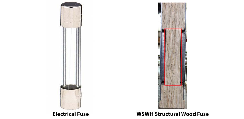
The WSWH wood fuse is designed to maintain its structural integrity until it reaches a certain force threshold resulting from lateral forces applied to the top of the panel. At lower loads consistent with design level forces, the structural integrity of the fuse element is maintained and the effective bending stiffness, and by extension the drift-limited allowable shear value, is maximized. The installation instructions for tightening the heavy hex nuts, which anchor the panel to the foundation, also play a critical role in maximizing initial stiffness. When the nuts are tightened to finger-tight plus a ½ turn, all system slack is removed from the shearwall assembly and the load-resisting elements are directly engaged.
Once the capacity of the structural fuse element is exceeded, it’s designed to facture in tension or compression in a controlled manner and at a predetermined force threshold in order to accommodate larger inelastic panel drifts. The load-carrying capacity of the panel is thus preserved, and additional energy-dissipating mechanisms are activated. The progression of WSWH behavior influenced by the fuse element as the panel migrates from elastic to inelastic behavior is shown below.
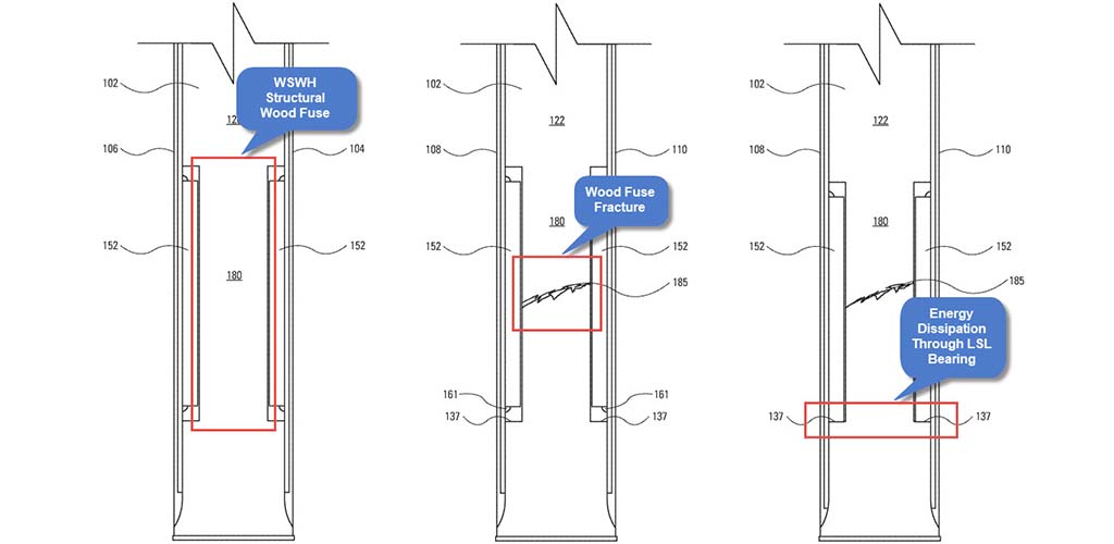
WSWH Structural Wood Fuse Progression — Intact, Post-Fracture, and Resulting Energy Dissipation
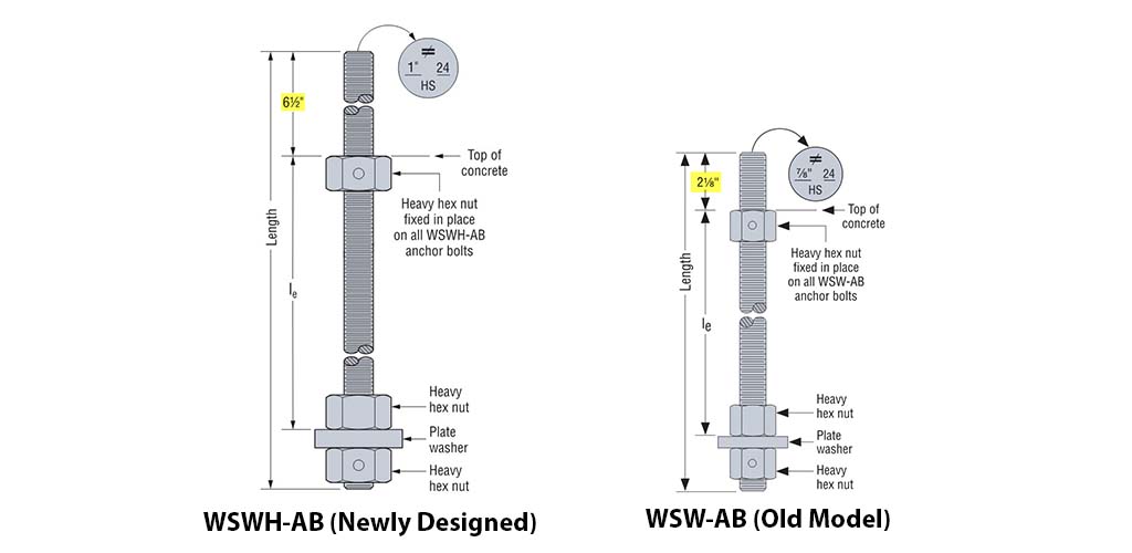
Finally, in order to both geometrically accommodate the structural wood fuse element and attach the WSWH panel to the foundation, the anchoring point was moved higher. We now have a preassembled anchor bolt featuring a greater vertical projection above the top of concrete at 6½” as opposed to the 2⅛” projection used with the WSW. The ancillary benefit of this extra bolt projection is that we have an additional source of energy dissipation; this time through the more traditional means of anchor bolt elongation. Now that we’ve taken a behind-the-scenes look at how it works, let’s dive into some of the key specification and installation details.
Simpler and More Streamlined
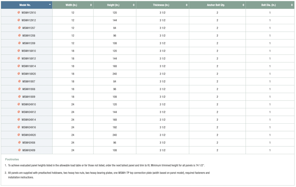
First, we’ve simplified the specification, distribution, and manufacturing processes by reducing the number of available models from 35 to 19 across the three panel widths as shown in the table below. This has been accomplished by reducing the number of panel models available at each nominal height to a single model. We’ve then set the actual panel height equal to the nominal panel height, e.g., the height of the WSWH24x8 is now equal to 96″ rather than being available at both 93.25″ and 96″ heights. The rationale behind the new streamlined options is that the panel is typically field-trimmed to a custom height based on job-specific requirements. In light of the versatility of the WSWH, there’s no need to attempt to define a specific target height for each nominal framed wall height, especially considering geographical variations in building practices and stud heights.
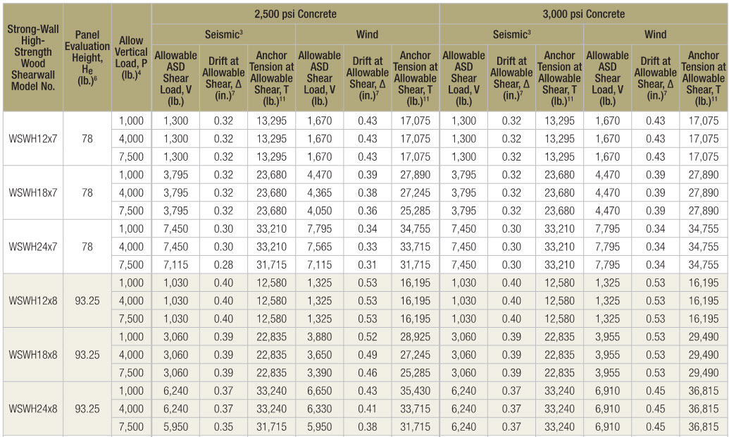
We have, however, continued to provide design values for the same model heights that you are accustomed to seeing, and in the same format, as shown in the load table below. Refer to the column titled “Panel Evaluation Height, He (lb.)” — design values have been evaluated at these defined panel heights just as they were for the WSW. And allowable shear, drift, and anchor tension values may be interpolated for intermediate heights just as before. In summary, start with the full-height panel, then trim and interpolate as necessary. I should mention that we still provide the ability to shim the top of the panel as needed, but those instances should be few and far between given the fact that anybody with a circular saw and a steady hand can easily trim the WSWH to the required height.
Wood Shearwalls Just Got Much Stronger
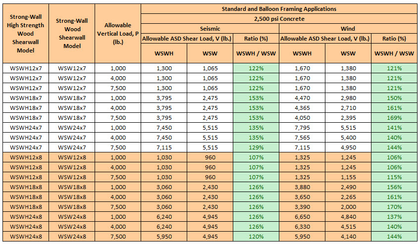
Since we’ve broached the topic of allowable loads, let’s discuss them further in the context of the differences between the WSWH and WSW. The table below provides allowable ASD shear values for the two panel types at the 7′ and 8′ model heights in both seismic and wind applications. Note the WSWH design values are approximately 25%-30% higher on average and sometimes as much as 70% higher than the corresponding WSW model. The improved loads shown in the table offer a great point of reference for comparison purposes, but the true benefit is that a designer may ultimately specify either narrower panels for a given application, or more importantly, potentially fewer panels in order to satisfy their job-specific loading requirements.
Now let’s assume that the allowable ASD shear values associated with the WSWH still don’t meet the jobsite demands, as may be the case for large multistory, multifamily projects. A designer might typically be inclined to specify a special moment frame. As a more economical alternative, we now offer back-to-back solutions for the WSWH when installed in both standard and garage portal applications. We require a minimum double 2×8 top plate for standard applications and a minimum 7″ x 11¼” header for garage portal applications. We’ve also designed the anchorage for both spread footings and grade beam foundations. The only thing left for the specifier to do is double the table load. Comprehensive design and installation information is provided in the code report and the structural installation details are available on the website.
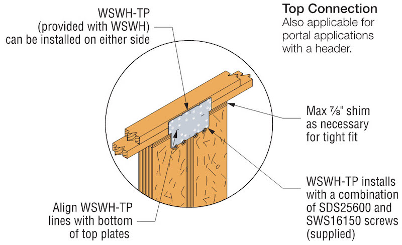
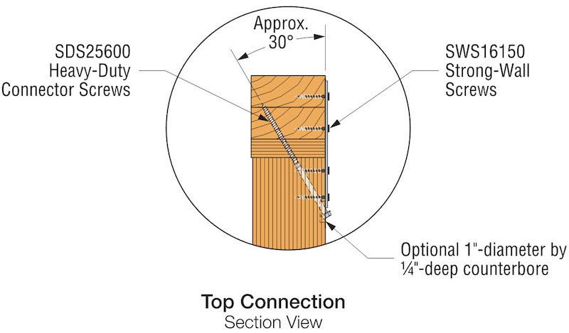
The top connection constitutes another difference between the WSW and WSWH. Instead of providing two different options, we’ve again simplified the product offering and now provide a single-sided connection option only. All necessary hardware and fasteners, including the newly designed Simpson Strong-Tie Strong-Wall screw (SWS), are included with the WSWH panel. There are a number of benefits to the single-sided connection worth noting. First, with a single-sided connection plate, there is no longer a need to shim the inside face of the panel to accommodate a second connection plate for cases where the net framing width is greater than 3½”. Further, back-to-back applications are far easier to construct when using a single-sided connection.
“Simplify, Simplify, Simplify” — Henry David Thoreau, Walden
Simplicity has been a common theme throughout this blog post so far, so let’s continue with that. I previously discussed the relative increase in allowable ASD shear loads with the WSWH. At the top end, the WSWH24x7 features an allowable ASD shear load of over 8,200 lb. for portal applications, which means the top connection must be capable of transferring that force from the header to the panel. A combination of Simpson Strong-Tie® Strong-Drive® SDS Connector screws and the new Strong-Wall screws (SWS), as shown in the graphics below, is required to develop the full allowable ASD shear load. However, as panel height increases, the allowable panel loads decrease and there is no longer a need to transfer the full force for which the connection was designed. With that in mind, the angled SDS screws may be omitted for panels over 100″ in height, with one caveat — the allowable out-of-plane load for cases where the angled SDS screws are omitted is generally lower than with full fastening, which must be kept in mind by the designer.
We just discussed the top connection; now let’s consider anchorage. Keeping with the theme of simplification, we’ve streamlined our anchor bolt product offering and now use the same 1″-diameter anchor bolt for all three panel model widths. This not only brings simplicity to the ordering process for the preassembled WSWH-AB anchor bolts offered by Simpson, but it also reduces the chances of installing the incorrect anchor bolt diameter in the field. Aside from the diameter, I previously discussed a critical difference between the WSWH anchor bolts and the WSW anchor bolts, but it’s worth mentioning again. Recall that the WSWH-AB anchor bolt has a vertical projection of 6½” above the top of concrete, whereas the old WSW anchor bolt features a 2⅛” vertical projection above the top of concrete. When the WSWH is specified, it’s important to ensure that the newly designed WSWH preassembled anchor bolts are also specified and installed. If the WSWH is specified and the old WSW anchor bolts have been installed, we have developed a fix for this misinstallation, but note that reduced loads may apply.
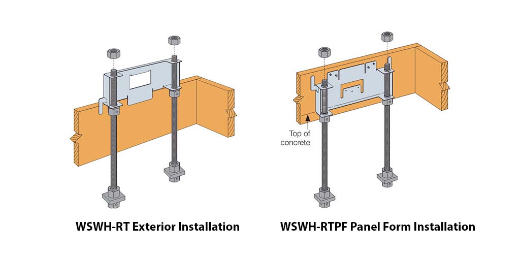
Finally, for the new anchor bolts, we have newly designed anchor bolt templates. We’ve developed options for standard, interior, brick ledge, and panel form foundation types as well as an extended leg option that locates the anchor bolts correctly so that the WSWH may be installed flush to the inside face of a 2×6 framed wall. A sampling of the newly designed anchor templates is depicted below.
 Stay Informed

All of the information discussed above, and much more, is included in our new Strong-Wall® Shearwalls catalog, C-L-SW21. The Strong-Wall® Shearwall Selector, which helps designers select the appropriate shearwall solution, will also be updated shortly with the latest Strong-Wall high-strength shearwall (WSWH) solutions for standard, balloon framing, portal, and raised floor applications. Finally, we are preparing to release solutions for raised floor, two-story stacked, wood beam, steel beam, and masonry applications shortly. Stay updated with the latest developments at www.strongtie.com.
