


In the last post, we described the primary structural and wood-related changes in the 2021 International Residential Code, Chapters 3 and 4. This post will continue with the primary changes to Chapters 5 through 8 of the IRC.

Decks
For the 2018 and the 2021 IRC, an informal group known as the Deck Code Coalition had been working to develop detailed prescriptive requirements for the safe construction of decks. For the 2021 IRC, seven of their proposals were ultimately approved, making significant improvements to the deck section.
One change made general improvements and expanded the use of the tables throughout the section. It clarified that decks are designed for either the live load or the ground snow load, whichever is greater. It revised the footing sizes in Table R507.3.1, allowing some smaller footing sizes for members with lower demand loads. The deck post height table was revised to make the post height based on tributary area of the post. Revised deck joist span tables, deck beam span tables, and deck ledger connection tables were added that cover 50, 60, and 70 psf snow loads in addition to 40 psf live loads. A new method of analyzing joist cantilevers resulted in a new deck joist span table with the maximum cantilever based on the adjacent joist span rather than the joist spacing.
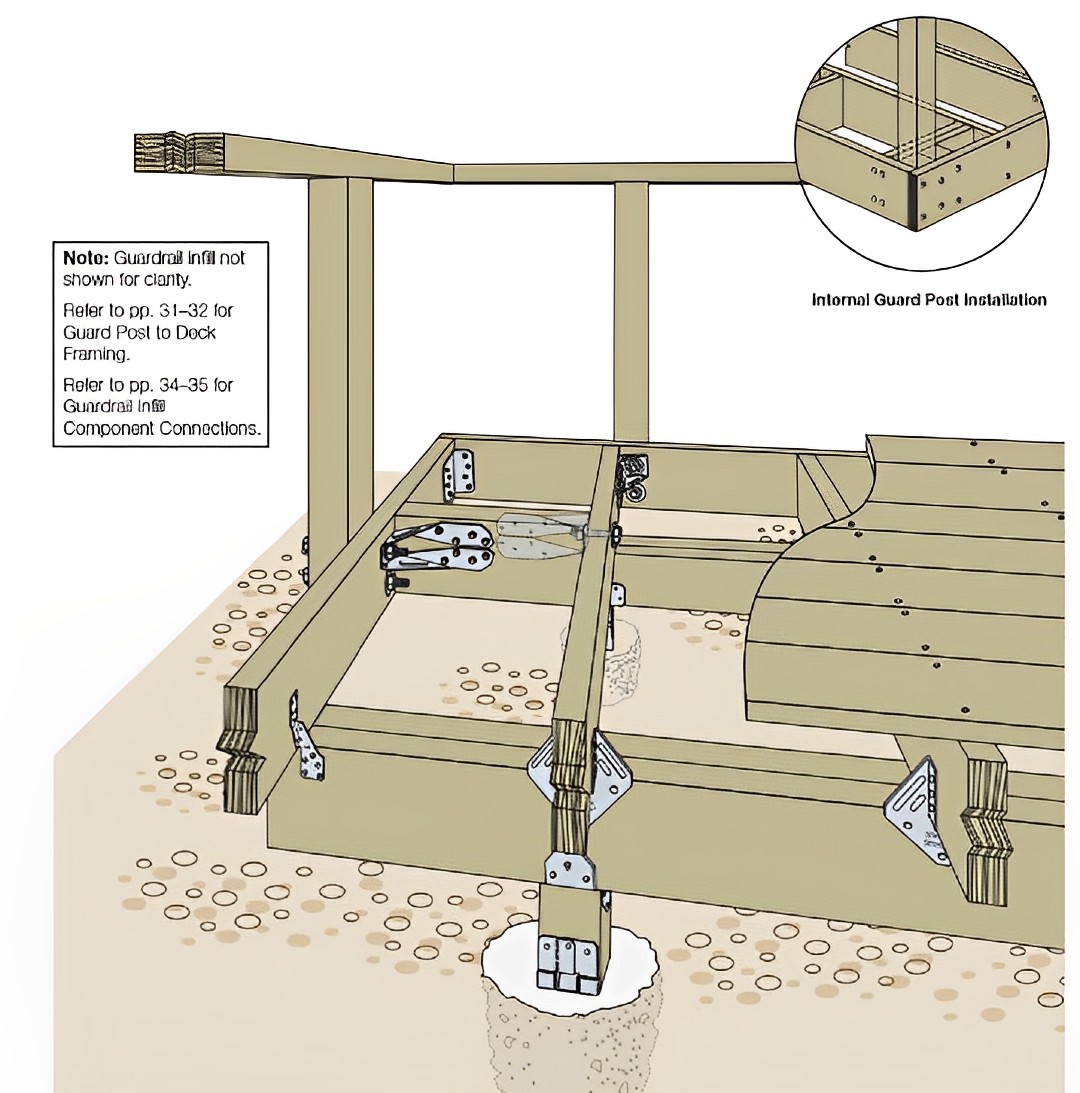
Another change provides generic instruction for construction of guards so they can resist adequate lateral load. While not providing exact details, the new Section R507.10, Exterior Guards, will reinforce that guard loads have to “be transferred to the deck framing with a continuous load path to the deck joists.” The new section states that where the guard post is connected to the side of a joist or beam, that joist or beam must be connected to adjacent joists to prevent rotation of the beam, and when the guard post is mounted on top of the decking, it must be “connected to the deck framing or blocking and installed in accordance with approved manufacturer’s instructions to transfer guard loads to the adjacent joists.” Previously, the Deck Code Coalition had attempted to put in actual prescriptive details for mounting of guard posts, but those had been disapproved, so they probably thought that this was the best they could do for now.
A couple of the changes dealt with installation of deck beams. One specifies that deck beams made of two pieces of lumber must be fastened together. The intent is to prohibit the practice of notching both sides of the support post and installing one beam member on each side. The beam spans are based on both beams being fastened together. A related change clarified application of deck beams, limiting the cantilever to one-fourth of the actual beam span, rather than one-fourth of the allowable beam span.
Another major change revised the table for spans of deck beams. As was also done for other tables, higher snow loads were covered. Furthermore, the deck beam span lengths in the table are now based on the Effective Deck Joist Span Length, not the actual joist span. The Effective Deck Joist Span Length is the actual joist span multiplied by a joist span factor that is determined by the ratio of the joist cantilever length divided by the supported joist span. This is meant to address the fact that the deck beam table is derived based on an assumed cantilever length of one-fourth of the joist span. When cantilevers shorter than that are used, the old table would be overly conservative, and the new factor accounts for that.
Finally, the treatment of deck board spans was revised. New columns were added to the joist spacing table for single spans of deck boards, and it was clarified that the entries for the existing columns were for multi-span boards.
For information on the use of Simpson Strong-Tie products with decks, take a look at our Deck Connection Fastening Guide, Connection Solutions to Meet the DCA6 Prescriptive Residential Wood Deck Construction Guide, Installation Options for Deck Lateral Load Connections, Code-Compliant Guardrail Post Connections, or Guard Post, Guard Rail and Baluster Installations Using Strong-Drive® Structural Fasteners.

Fasteners
There were several changes to IRC Tables R602.3(1) and R602.3(2) that affect wood-frame fastening. In Table R602.3(1), two new lines were added for fastening of blocking between rafters or trusses not at the top plate, one for toe nails and one for end nails. The fastening of sheathing to framing was split into two rows, one for subfloor and wall sheathing, and another row for roof sheathing. Roof sheathing fastening spacing was changed from 12″ to 6″ on center at intermediate supports for 8d common and RSRS-01 nails. The 12″ nail spacing for 10d common or 8d deformed shank nails was maintained. This is due to the new higher roof components and cladding loads in ASCE 7-16. New language was added in footnote A that specifies “nails used for framing and sheathing connections are carbon steel,” and that “Connections using nails and staples of other materials, such as stainless steel, shall be designed by accepted engineering practice or approved under Section R104.11.” This is to address the recently documented fact that stainless steel fasteners withdraw from wood easier than carbon steel fasteners, so the assumed values used to derive this table would not apply to stainless steel fasteners. Lastly, a new Note g was added to Table R602.3(2), the Alternate Attachments table that prescribes the use of staples and alternate sizes of nails. It states that “Alternate fastening is only permitted for roof sheathing where the ultimate design wind speed is less than or equal to 110 mph, and where fasteners are installed 3″ on center at all supports.”
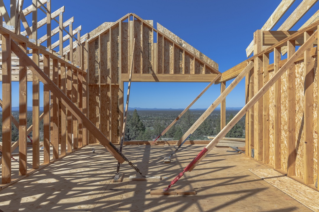
Wall Bracing
Although there were fewer than usual, there were still several changes made to the IRC Wall Bracing section. One significant change was to Section R602.10.1.2. It was retitled from “Offsets along a braced wall line” to “Location of braced wall lines and permitted offsets.” The 2018 IRC allowed the braced wall line to be offset not more than 4′ from the exterior walls without limitation. A building designer would be able to offset all their braced wall lines 4′ toward the interior of the structure, therefore reducing the required length of bracing, while still meeting the letter of the IRC. The 2021 wording will prohibit such an extent of offsetting, requiring that “Each braced wall line shall be located such that no more than two-thirds of the required braced wall panel length is located to one side of the braced wall line.”
Another change dealt with placement of braced wall panels at the ends of braced wall lines. In Seismic Design Categories D0, D1, and D2, braced wall panels have to be located at the end of braced wall lines, except that Methods WSP, BV-WSP, and continuous sheathing methods can begin up to 10′ from the end of the braced wall line provided a 24″-wide panel is installed at the building corner, and the panel closest to the end of the braced wall line has an 1,800 lb. hold-down device installed. A new exception was added to also allow a Method PFH or ABW to be installed up to 10′ from the end of the braced wall line, since these methods will also have holdowns with at least 1,800 lb.
In Table R602.10.3(3), which lists bracing lengths based on Seismic Design Category, bracing methods PFH, PFG, and ABW were added to the column heading with method WSP, in the same place they are listed when used to resist wind loads.
As mentioned in the previous IRC post, there were several changes meant to reinforce the limitations on use of wall bracing in high seismic areas. Tables R602.10.3(3), R602.10.3(4), and R602.10.6.5 were modified to remove illustrations for three-story houses in SDC D2, and add a footnote that “One- and two-family dwellings in Seismic Design Category D2 exceeding two stories shall be designed in accordance with accepted engineering practice.” Similarly, in Section R602.10.6.5, the statement that “Townhouses in Seismic Design Categories D0, D1, and D2 with stone or masonry veneer exceeding the first-story height shall be designed in accordance with accepted engineering practice” was moved to the beginning of the section, and the statement that “One- and two-family dwellings in Seismic Design Category D exceeding two stories and having stone or masonry veneer shall be designed in accordance with accepted engineering practice” was added.
Also in Section R602.10.6.5 related to houses with brick veneer, the section was rewritten to clarify the three conditions that might be encountered— veneer on first floor only, veneer exceeding first-story height, and limited veneer exceeding first-story height. The changes appear to be editorial only.
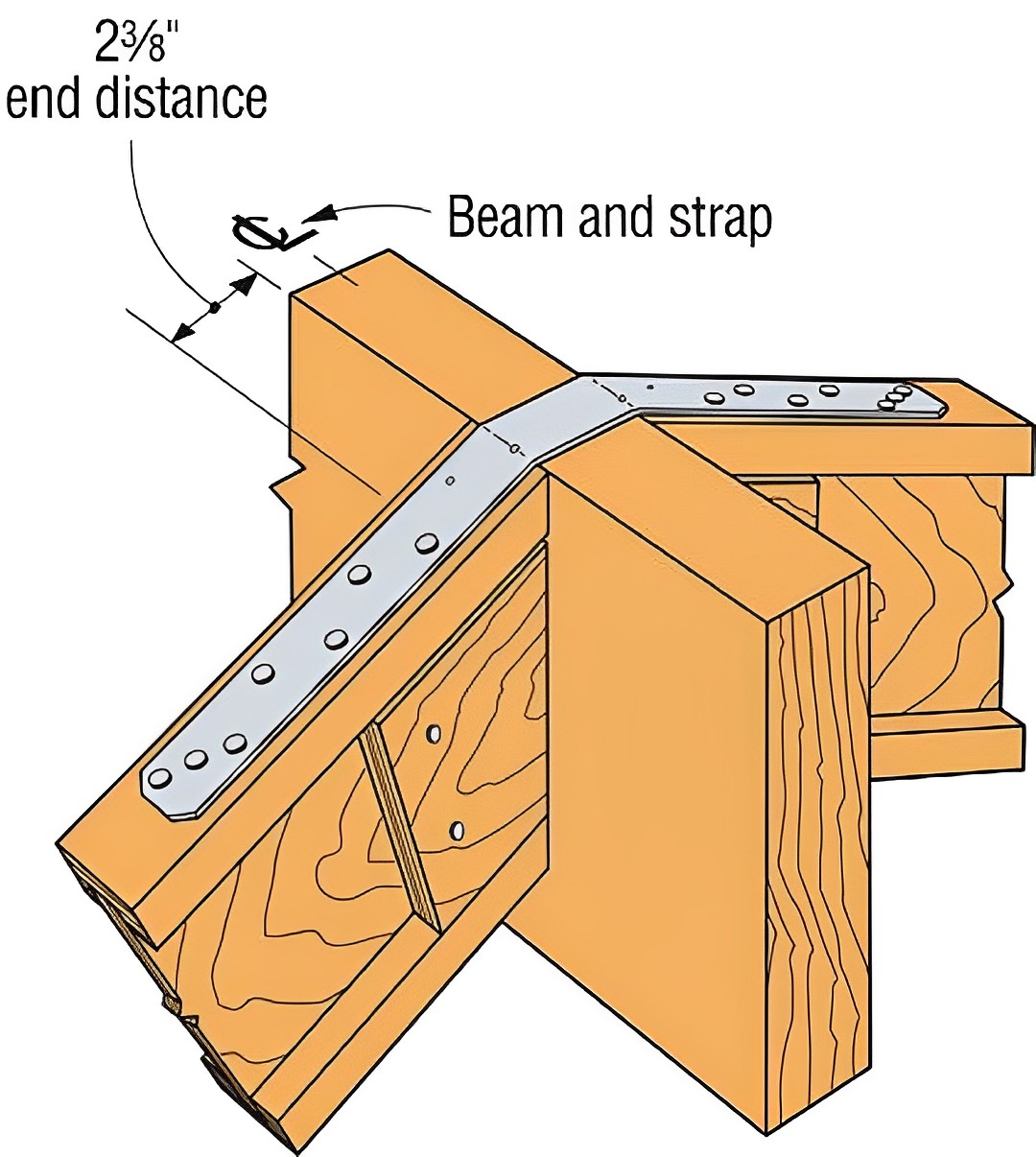
In Figure R602.10.6.2, which describes construction of bracing method PFH, a note that the strap-type hold-down in PFH must be installed with manufacturer’s edge distance was added. This is necessary to ensure that the allowable load of the strap-type hold-down can be achieved. Both Simpson Strong-Tie and MiTek recommend that their strap-type hold-downs be installed with a minimum of 1/2″ end distance.

Another change was the removal of a limitation that no more than four CS-PF portal frames could be used on a single wall line. The last wall bracing change was to Section R602.10.10.1, which deals with bracing of cripple walls in Seismic Design Categories D0 and D1, and townhouses in SDC C. It adds requirements to clarify that only bracing methods WSP and CS-WSP are permitted in these higher seismic areas.
For help with wall bracing and the use of Simpson Strong-Tie products in wall bracing, refer to Connector Solutions to Meet the Wall Bracing Requirements of the International Residential Code or the Wall Bracing Length Calculator web app.

Walls/Soffits
There are a couple of structural changes to note in Chapter 7. One was to Tables R703.15.1 (Cladding Fastening) and R703.15.2 (Furring Fastening). It states that the thickness of wood structural panel sheathing can count toward the minimum fastener penetration depth when the panels have the same minimum specific gravity as that required for the studs. A second change added a new section, R704, on soffits. The new section adds requirements for construction of soffits where design wind pressure exceeds 30 psf. This addresses an area that has been identified in recent storms as a weak link in the building envelope. While soffits might not seem structural, their failure in wind events allows wind and water into the attic, at best ruining the ceiling and insulation.

Roof Framing
For the second year in a row, the roof framing section was significantly rewritten. One change dealt with construction of the rafter peak and ridge straps when they are used to replace collar ties. Part of the change clarified that when the rafters are connected directly opposite one another with a gusset plate, collar ties or ridge straps are not required. The second part clarified the installation of the ridge strap to state that they must be “nailed to the top edge of each rafter with a minimum of three 10d common (3″ × 0.148″) nails with the closest nail no closer than 2 3/8″ from the end of the rafter.” This matches up with Simpson Strong-Tie’s recommendations for placement of nails at ends of wood members.
A couple of changes were made to the requirements for resisting rafter thrust, where weight on the rafter system causes them to push out on the tops of the exterior walls. One change to Section R802.5.2 clarifies the three cases for resisting rafter thrust: ceiling joists in the lower third of the rafter height and used to directly resist thrust; ceiling joists installed above the lower third of the rafter height that are not permitted to be used to resist rafter thrust; and ceiling joists that are not parallel to rafters. In each case, either the ends of the rafters are tied together with a continuous tie, or a ridge beam must be provided. In addition, the construction of laps or joints in ceiling joists used to provide the continuous tie was clarified. Table R802.5.2 gives the fastening of ceiling joists to rafters in order to transfer the rafter thrust into the joist. This table was revised to slightly reduce the number of nails required for the ceiling joist to rafter connection.
A final roof framing-related change was to the section requiring rafter bearing, R802.6. The change clarifies when bearing is required for the top ends of rafters by adding the sentence “Where the roof pitch is greater than or equal to 3:12 (25% slope), and ceiling joists or rafter ties are connected to rafters to provide a continuous tension tie in accordance with Section R802.5.2, vertical bearing of the top of the rafter against the ridge board shall satisfy this bearing requirement.” This means that, in a normal rafter/ceiling joist/ridge board configuration, 1 1/2″ bearing for vertical forces is not required, as the rafter is just pushing horizontally against the ridge board. However, if there were rafters with no ceiling joists or other horizontal tie at the bottom, there would be a requirement for vertical bearing at the ridge beam, because the ridge beam is providing vertical support for the rafter.
For more information on stick-frame roofing, check out our online course “Code Requirements for Conventionally Framed Roofs”.
We plan to publish another blog summarizing the 2021 International Building Code changes in upcoming weeks. What other code-related subjects would you like to see covered here?
