

Within the world of multifamily construction, manufacturers design and detail the multistory continuous threaded rod holdowns used as shearwall overturning restraints. The Strong-Rod® anchor tiedown system (ATS) is Simpson Strong-Tie’s solution for the industry and has been the subject of many SE Blog topics in the past.
At Simpson Strong-Tie, we pride ourselves on providing relevant tested solutions and research that drives real-world decisions within the engineering community. Additional ATS research and testing previously featured on this SE Blog include UL Listing as Through-Penetration Firestop System, Rod Welding, Brittle Failure, and Alternative Connections, and Anchor Reinforcement for Concrete Podium Slabs. This blog will focus on a topic that is ambiguous and not clearly defined within the AISC Steel specifications or other documents — namely, what rod area should be used to determine rod elongation?
Before we delve into our latest research project, let’s discuss a few important points for system deformation:
1. Threaded rod systems have many components that make up individual holdown runs, most of which (e.g., threaded rods, bearing plates, anchors) are designed in accordance with applicable building code reference standards (AISC, NDS, ACI, etc.). Within the industry, the only components code listed in code reports are proprietary shrinkage compensation devices. For Simpson Strong-Tie ATS solutions, these are the ATUD/TUDs and RTUDs, which are code listed in ICC-ES ESR-2320.
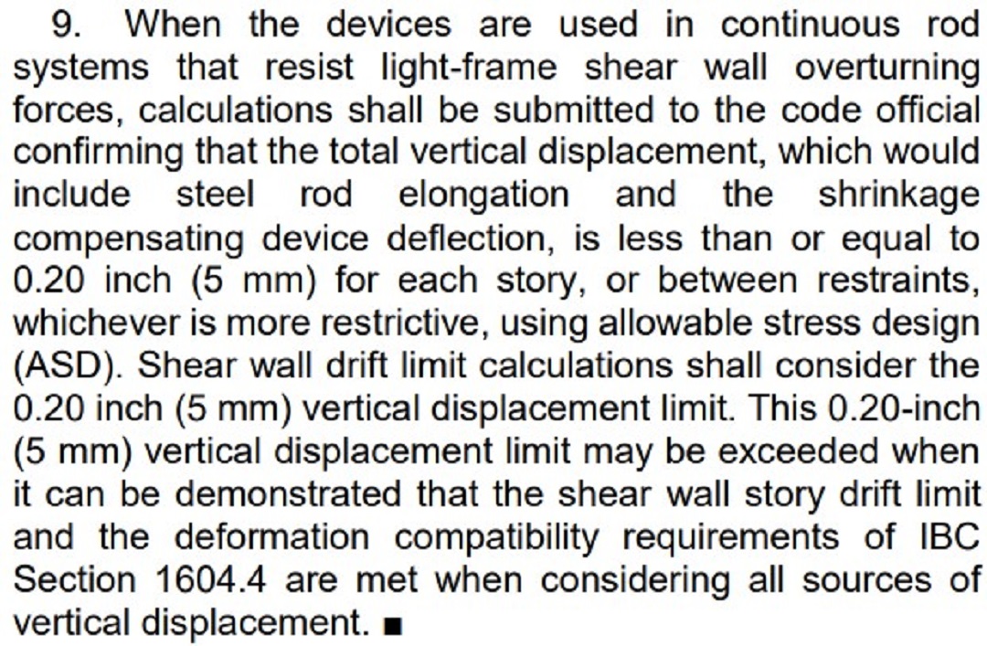
2. Shrinkage compensation devices are tested in accordance with ICC-ES Acceptance Criteria AC316. As stated in Section 6.0, note 9, unless otherwise demonstrated, system deformation shall include steel rod elongation and shrinkage compensation device deformation and should be limited to 0.20″ (ASD) per level/floor, by default, but may be exceeded if justified by the designer.
Comparing this limit in AC316 to other publicly developed standards, it follows similar recommendations. ICC-ES AC155 (the Acceptance Criteria for Hold-downs attached to wood members) is used to develop published allowable loads of proprietary holdowns such as the Simpson Strong-Tie HDUE series of screw holdowns. AC155 sets a 0.250″ deformation limit at strength level loads. As mentioned in this SE Blog (So, What’s Behind A Structural Connector’s Allowable Load? (Holdown Edition), story-drift is a critical component to shearwall performance and the deflection of holdowns has a significant effect on the total drift. What happens when shearwall drift is excessive? Our testing of site-built shearwalls with and without holdowns, as stated in this blog (Use of Holdowns During Shearwall Assembly), suggests what might happen when other components of the site-built shearwalls (e.g., nails) are forced to resist overturning in addition to their intended role (e.g., transfer shear to sill plate).
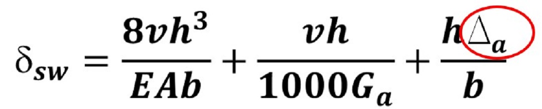
3. Sources of deformation for rod systems shall be considered by designers when they calculate the maximum shearwall deflection, δsw, determined per equation 4.3-1 of the 2021 AWC Special Design Provisions for Wind and Seismic (SDPWS). The SDPWS defines Δa as the “vertical deformation of the wall overturning anchorage system (including but not limited to fastener slip, device elongation, rod elongation, and uncompensated shrinkage) …,” and should be provided by the manufacturers within their calculation package (generally shown in ASD, and therefore must be converted).
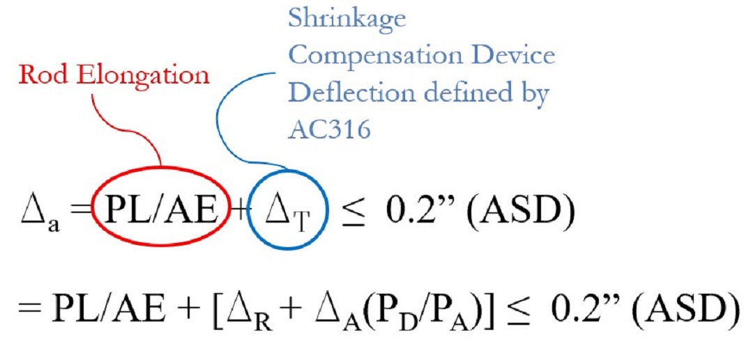
4. The American Institute of Steel Construction (AISC) provides designers with the necessary guidance as well as required provisions for designing threaded rods within AISC 360-16 Specifications for Structural Steel Buildings. While there are provisions for calculating the rod strength (e.g., AISC 360-16 eqn. J3-1), calculating elongation is not listed, and one must refer to general material characteristics equations. From our strengths and materials classes, we know that when an axial load is applied to a bar or rod, the amount of elongation can be calculated using the following equation: Δrod = PL/AE
Where:
- P = the load (kips)
- L = the length of the rod (in)
- A = area of the rod (more discussion on this in a few) (in.2)
- E = Young’s Modulus (29,000 ksi)
5. Rod elongation and shrinkage compensation device deflection both contribute to the holdown deflection, Δa, and can be written as:
6. A calculation package should be included with a manufacturer’s submittal for inclusion into the designer’s construction documents and should incorporate this information.
This leads us to the question, what Area, A, should be used when calculating rod elongation?
Table 7-17 (AISC 325-17) lists three different areas for each bolt diameter; gross bolt area, minimum root area, and net tensile area (further defined by the equation in footnote [a]).
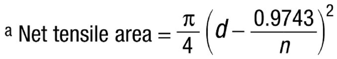
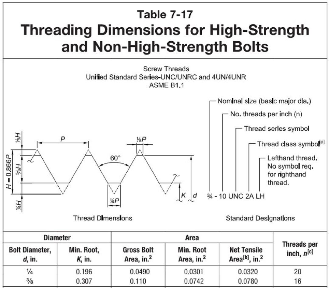
Neither AISC 325-17 nor 360-16 provides written guidance of which area, A, to use when calculating rod elongation, Δrod = PL/AE. By observation, the smallest of the three areas, Aroot, would provide the largest calculated elongation. Therefore, Agross, the largest of the three values, would result in the smallest deflection. Anet tensile would result in a value between the other two. For this discussion, we will use the term effective area, Aeffective, and stress area, Astress, interchangeably with net tensile area, Anet tensile.
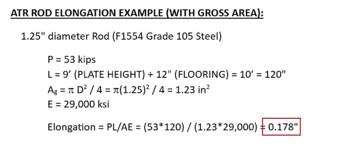
Many years ago, when Simpson Strong-Tie entered the threaded rod industry, there were several discussions of which area to use. We landed on the use of the effective area, Aeffective. In recent years, the approach Simpson Strong-Tie has historically taken (use of effective area), has faced scrutiny due to lack of data and guidance within the industry. We wanted to better understand which approach best represents the actual rod performance. Some believe the use of gross area is best. As mentioned earlier, this results in the smallest rod elongation amongst all rod areas. Comparatively speaking, when considering the same demand load, one design approach might allow for a smaller rod diameter at any given floor as it is less than the deformation limit, yet the other design approach would require a larger rod diameter so as to not exceed the deflection limit. Let’s explore an example:
Calculating total deformation, Δa, would lead to the following:
- Gross Diameter (1.25″ diameter rod)
- PL/AE = 0.178″
- ΔT = 0.02″ (assume maximum deflection for ATUD14)
- Δa = PL/AE + ΔT = 0.198″ < 0.20″ (okay)
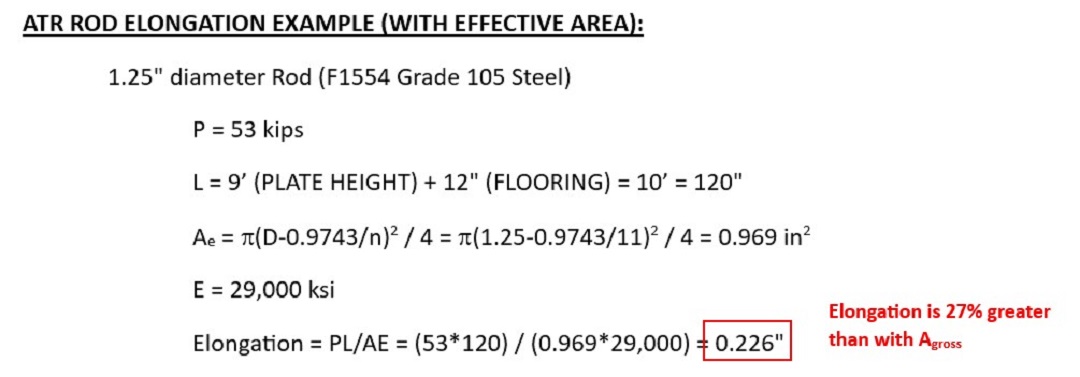
- Effective Area (1.25″ diameter rod)
- PL/AE = 0.226″
- ΔT = 0.02″ (assume maximum deflection for ATUD14)
- Δa = PL/AE + ΔT = 0.246″ > 0.20″ (no good, try larger diameter rod)
- Effective Area (1.375″ diameter rod)
- PL/AE = 0.190″
- ΔT = 0.02″ (assume maximum deflection for ATUD14)
- Δa = PL/AE + ΔT = 0.21″ > 0.20″ (no good, try larger diameter rod)
- Effective Area (1.5″ diameter rod)
- PL/AE = 0.156″
- ΔT = 0.02″ (assume maximum deflection for ATUD14)
- Δa = PL/AE + ΔT = 0.176″ < 0.20″ (okay)
Using the effective area compared to the gross area requires the rod to be two diameters larger to satisfy the deformation limit recommended by ICC-ES AC316. The design approach leads to two completely different system performances and costs.
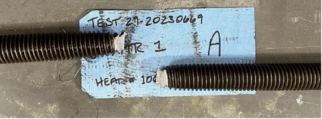
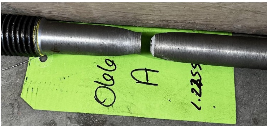
To better understand actual performance, Simpson Strong-Tie recently completed a test program to compare fully threaded rod performance to their gross-bodied diameter counterparts. Here is what we evaluated:
- Diameters tested: 5/8″, 7/8″, 1″, and 1-1/4″
- Deformation measured over 8″ lengths
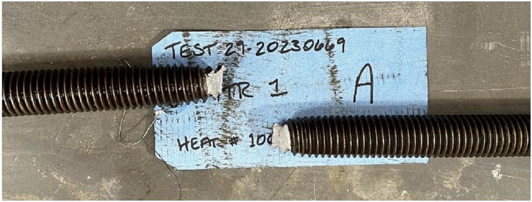
- Standard strength F1554 Grade 36 material was used (note, strength of material does not impact elongation)
- All material tested came from the same heat number
- Each diameter had fully threaded rods obtained from a third-party rod supplier
- For the gross bodied diameters, larger diameter threaded rods were ordered and machined to match the gross diameter of the fully threaded version.
- Eight tests of each diameter were completed; four fully threaded and four full-bodied rods
The following graphs show the results of the completed testing. In each graph, there are four different lines. In the upper left and lower right corners, are the corresponding indexes to the color of the lines closest to them.
The calculated gross area uses the area calculated from the measured diameter of the gross body diameter rods. Likewise, the calculated effective area uses the measured gross diameter of the threaded rods and the corresponding equation for net tensile area from Table 7-17 footnote [b].
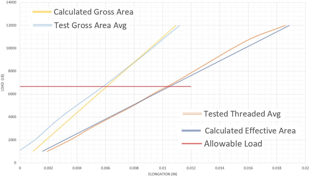
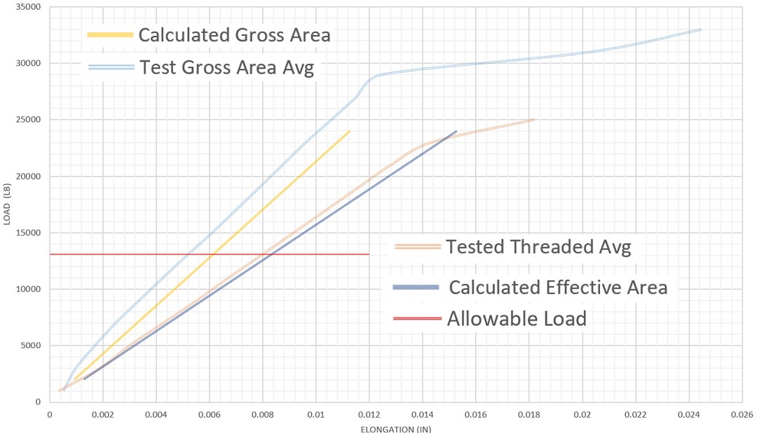
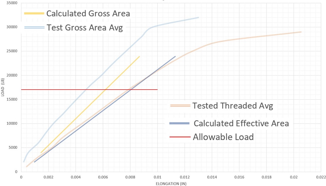
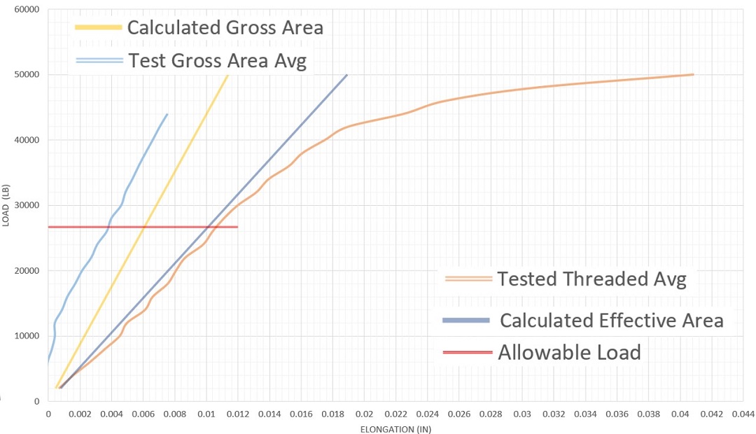
Fully threaded rod is supplied and installed on the jobsites and therefore we want to perform calculations that best represent what is happening in the field. Each test series shows that the calculating elongation based on effective area, Aeffective, best represents how threaded rod actually deforms in testing. The use of gross area, Agross, underestimates the actual elongation of the fully threaded rod, which yields unconservative results.
To ensure accurate rod elongation calculations, Simpson Strong-Tie recommends the use of the effective/net tensile area when calculating deformations with threaded rod holdown systems to better estimate the actual deformation. With rod systems being designed by rod manufacturers today, we recommend the following be added to your general notes to communicate the desired performance:
- Δa shall be the total vertical elongation of wall anchorage system (including rod elongation calculated with net tensile area, device deflection, and any other components of the wall anchorage system).
- Δa shall be limited to 0.2″ (ASD) per level unless otherwise noted.
- Note: Check with your local building jurisdictions as there may be more restrictive requirements.
