

In North America, CLT and mass timber construction have garnered considerable press over the last few years, both inside the building industry and beyond. The burgeoning development has inspired new research centers and at least one annual conference — now in its eighth year and attracting scores of presenters and exhibitors and hundreds of attendees from around the world. Numerous observers are even heralding mass timber, or tall timber, as the necessary future of the fast-growing built environment.
For Simpson Strong-Tie, this is a perfect fit. We got our start in wood connectors and always love a new engineering challenge. We take pride in finding solutions for building stronger, safer structures in an economical and socially responsible way. So, naturally, we welcomed the opportunity to put our structural ingenuity and our passion for tested solutions at the service of the mass timber industry.
We have published a new catalog of connectors, fasteners and other products especially suited for mass timber construction, along with a mass timber solutions page on our website.
CBH = Consummate Backstage Hero
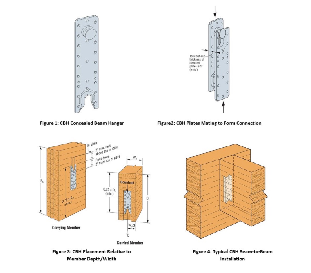
Prominent among the connectors featured in our mass timber products catalog is the CBH concealed beam hanger — hardware that hides its structural strength within a timber connection.
This connector takes advantage of the ability of computer modeling and computer numerical control (CNC) machining to deliver glulam members to a job site precut to precise dimensions with concealed connectors preinstalled. The CBH consists of paired 3-gauge galvanized steel plate components, each with a welded stud on one end and a slot on the opposite end (Figure 1). One connector is installed on the joist or carried beam and another is installed (in an inverted orientation) on a column or carrying beam (Figure3). Either or both members may be routed to recess the plate(s) as specified for the application. Before shipping, the fabricator installs the hangers easily on both members (whether routed or unrouted) with Simpson Strong-Tie® Strong-Drive® SDS Heavy-Duty Connector screws. At the jobsite, the members are assembled by mating the two CBH plates. Each connection provides a ± 1/32″ beam length tolerance, making the beam easier to crane into place. Concealment of the connector enhances not only the architectural aesthetics of the timber but also the fire resistance of the connection, as we will see later in this post.
The CBH is load rated and code listed per ICC-ES ESR-2552.
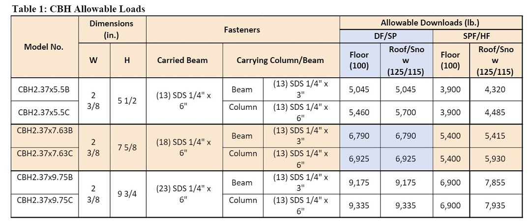
- Table loads for CBH require a 5 1/2″ minimum carried beam width. For 5 1/8″ ≤ carried beam width < 5 1/2″, multiply allowable load by 0.81. For 3 1/2″ ≤ carried beam widths < 5 1/8″, refer to L-C-CBH4XSKEW at strongtie.com.
- For installation of Simpson Strong-Tie Strong-Drive SDWC15600 screws into the top of the beam for uplift: Install screw at 45˚ angle 2″” from the end of the beam. Minimum spacing requirements for SDWC15600 screws are 1/2″ edge distance and 1″ screw spacing when using multiple screws. Uplift capacity is 555 lbf for DF/SP and 548 lbf for SPF/HF per screw. Use multiple screws for additional uplift.
- For skewed installation of the CBH, refer to L-C-CBH4XSKEW at strongtie.com.
- CBH may be installed on supporting vertical columns using 1/4″ x 3″ SDS screws with reduced download capacities. Beam-to-beam allowable download capacities may apply.
- Allowable loads for double connections are equivalent to the allowable load of one connection multiplied by 2.
Ongoing research
Since the release of our mass timber products catalog, we haven’t stopped investigating the performance and capacities of the CBH hanger. Continued testing has revealed new data for use in various applications.
Connecting timber to structural steel members
One application we’ve researched involved using the CBH to connect glulam joists to structural steel carrying members. In this connection, the carried plate is attached to the joist with Strong-Drive® SDS Heavy-Duty Connector screws whereas the carrying plate is either welded to the steel supporting member or fastened to it with #14 self-drilling screws (but should never be attached using a mix of screws and welds). When welding, use fillet welds spaced symmetrically from top to bottom on each side of the plate.
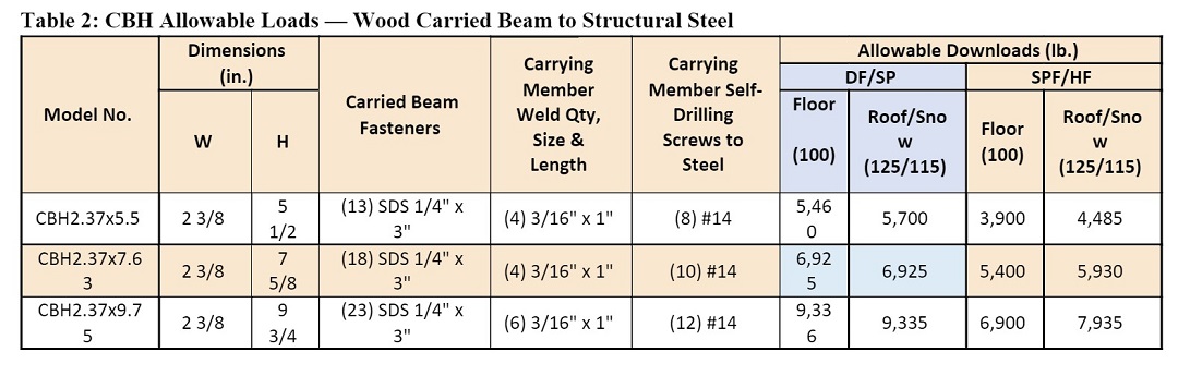
- Installation requires tabulated SDS screws to the carried wood beam and either welds or self-drilling metal fasteners (not both) to the carrying steel member. Allowable loads are applicable to either installation.
- Welded loads assume E-70XX weld material.
- Caution: Welding galvanized steel may produce harmful fumes; follow proper welding procedures and safety precautions. Welding should be in accordance with AWS standards.
- Welds must conform to the current AWS D1.1 structural welding code for steel.
- Welded connections should only be performed by skilled, qualified welders.
- Welded connections require a minimum of 3″ wide flat surface area to accommodate the width of the connector and the welds.
- Loads are based on attachment to structural steel with a minimum yield strength, Fy, of 36 ksi.
- Self-drilling metal fasteners shall be in compliance with ASTM C1513.
- Self-drilling 1/4″-diameter metal fasteners may be substituted for self-drilling #14 metal fasteners. Maximum thickness of the framing member must not exceed the maximum total drilling thickness for the metal fasteners.
- To ensure proper installation of CBH connectors with self-drilling metal fasteners, head depth of screws must not exceed 0.250″ and head diameter must not exceed 0.500″.
- Connections are not evaluated for uplift.
- Minimum required fastener length is the greater of 3/4″ and the minimum length required for the fastener to extend through the steel connection a minimum of (3) exposed threads per AISI S240-15, Section C4.1.2.1.
Connecting timber to grout-filled CMU and concrete
Another application we researched was using the CBH to connect a wood carried member to grout-filled CMU (GFCMU) or concrete carrying members. In this connection, the carried plate is attached to the carried wood member with Strong-Drive® SDS Heavy-Duty Connector screws and the carrying plate is fastened to GFCMU or concrete with Titen TurboTM masonry screws.
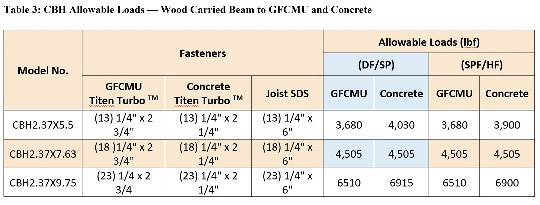
- Concrete shall have a minimum compressive strength of f’c = 2,500 psi.
- Grout-filled CMU (GFCMU) shall have a minimum compressive strength of f’m = 1,500 psi.
- Products shall be installed such that the Titen Turbo™ screws are not exposed to weather.
- Titen Turbo screws are Simpson Strong-Tie® concrete and masonry screws (hex-head model required).
- Installation on GFCMU: A minimum fastener side edge distance of 3 7/8″ and a minimum top fastener end distance of 1 1/2″ is required (refer to figure 1) for full table downloads. For a minimum fastener side edge distance of 1 1/2″ and a minimum top fastener end distance of 1 1/2″, allowable downloads are 0.63 of the table downloads.
- Installation on concrete: A minimum fastener side edge distance and top fastener end distance of 3″ is required (refer to figure 1) for full table downloads. For a minimum fastener side edge distance of 3″ and a minimum top fastener end distance of 1 3/4″, allowable downloads are 0.95 of the table downloads. For a minimum fastener side edge distance and top fastener end distance of 1 3/4″, allowable downloads are 0.60 of the table downloads.
- Connections are not evaluated for uplift.
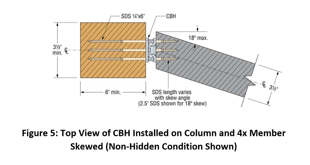
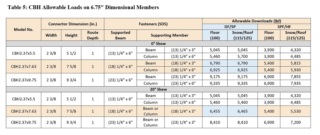
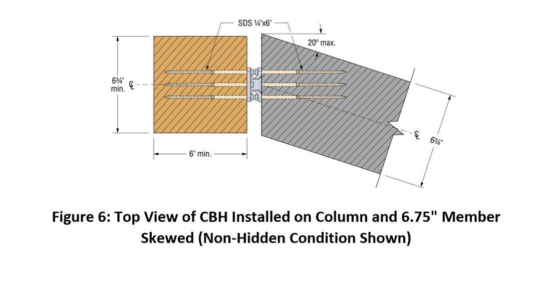
Attaching joists at a skew
Another application that we’ve investigated since we published our mass timber catalog involves attaching joists to their supporting members at a skewed orientation. Specifically, we evaluated the CBH as installed on 4x dimensional wood columns (4×8 minimum) to support a 4x dimensional joist with a maximum horizontal skew of 18° either left or right; and secondly as installed on 6.75″ wide glulam (GL) columns to support a 6.75″ GL joist with a maximum horizontal skew of 20° left or right.
Table 4 provides allowable downloads for the CBH attached to 4x dimensional wood members skewed 0° to 18°. Table 5 provides allowable downloads for the CBH attached to the 6.75″-wide GL members and skewed 0° to 20°.
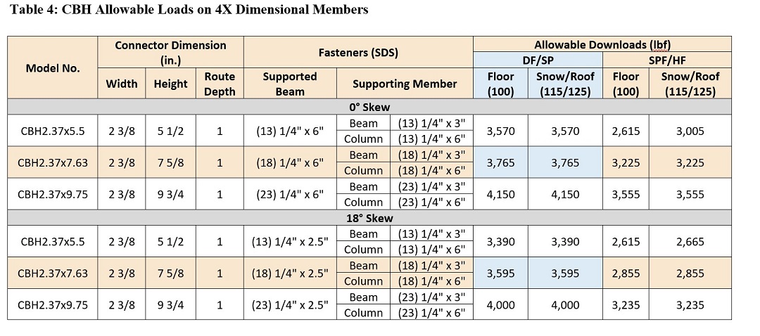
- See footnote for Table 5 below.
- Member sizes based on minimum edge distances will achieve tabulated allowable downloads but do not consider char edge distances for required fire ratings.
- Tabulated fasteners and allowable loads require the CBH to be fastened the beam and column centered on both the face of the supporting column and the end of the carried beam with the end of the carried beam miter cut to the left or right for the required skew angle.
- For skewed 4x supported beam conditions, SDS 1/4″ x 3″ screws are allowed in the supporting column for beam-to-column installations when column widths are 4.75″ or greater.
- Connections are not evaluated for uplift.
- For the CBH installed on 4x members, the supported beam fastener length must be adjusted based on skew as follows:
Skews 0 to 5 degrees = 6″ SDS; skews >5 to 7.5 degrees = 4.5″ SDS; skews >7.5 to 12.5 degrees = 3.5″ SDS; skews >12.5 to 18 degrees = 2.5″ SDS
For more information on these applications and our allowable load determinations at varying skew angles, see the engineering letter (L-C-CBH4XSKEW21).
Minimum allowable carried beam dimensions based on fastener edge distances
We also did some research regarding the minimum allowable width and depth of carried beams in relation to fastener edges. The table below shows dimensions for specific fastener edge distances as well as the larger minimum edge distances required for one-hour and two-hour fire resistance ratings per ASTM E119 testing.
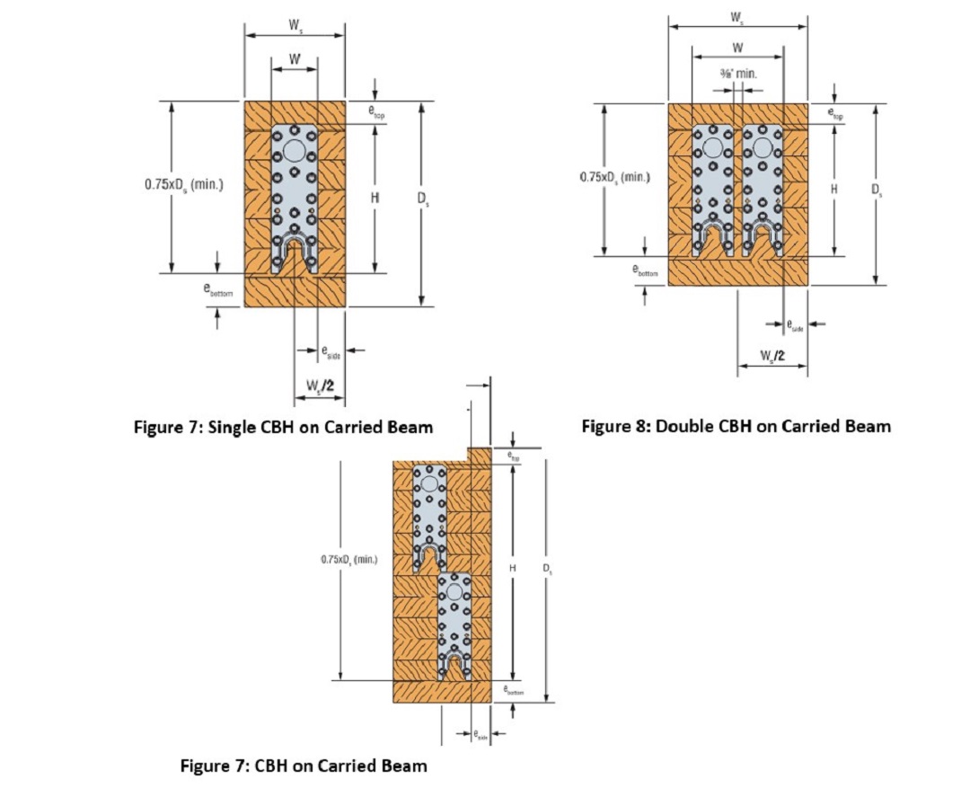
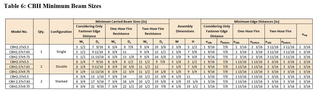
- Side edge distances for supporting vertical columns must meet or exceed the eside table values for the supported beam.
- For single-configuration conditions where fire resistance need not be considered and 5 1/8″ ≤ carried beam width < 5 1/2″, see CBH Allowable Downloads table footnotes for load reduction. For 3 1/2″ ≤ carried beam width < 5 1/8″, refer to L-C-CBH4XSKEW at strongtie.com.
- Minimum carried beam sizes and edge distances for one-hour and two-hour fire resistance are based on ASTM E119 fire testing. Test specimens included 3M Expantrol E-FIS intumescent fire seal at the beam-to-column interface. Substitutions for the 3M Expantrol are allowable provided they meet or exceed the 3M Expantrol’s specifications for flame spread, smoke developed index, intumescent activation temperatures (expansion rate), and service temperatures.
- Top edge distances in the table assume full coverage of the top of the carried beam. A full coverage condition occurs when the top of the beam is not directly exposed to fire (i.e., roof or floor members are attached to the top of the carried beam and provide complete continuous cover to the top of the beam). For conditions where the top of the carried beam is exposed to fire, increase the minimum top edge distance to eside for the installed condition.
- For one-hour and two-hour fire resistance, the gap between the end of the carried member and the face of the carrying member shall not exceed 1/4″.
Note: When installing CBH configurations of two or more connectors, additional care must be taken to ensure mating CBH connectors will fit together appropriately in the field. Accordingly, confirmation that assemblies mate properly prior to field installation is strongly advised. Allowable loads for multiple CBH assemblies are equivalent to the published individual CBH allowable loads multiplied by the number of connectors.
Facing the heat — ASTM E119 fire-resistance testing
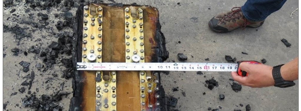
Thanks to its thickness, mass timber has been demonstrated to burn much more slowly than dimensional wood members. In a typical scenario, a timber member’s outside chars and prevents oxygen from reaching the core, which thereby retains its structural strength.
Connections, however, are often the most vulnerable part of a given structure because of the number of separate elements involved and the nature of their interface. In the case of fire resistance, metal connectors and fasteners introduce a specific failure hazard because of their heat conductivity. Metal fasteners in particular will transfer heat into the connected timber members, which can lead to increased charring, reduction in timber strength, and, ultimately, premature failure of the connection — the timber doesn’t retain sufficient strength and stiffness to resist screw tension forces and prevent shear pullout.
Apart from the aesthetics, concealed connectors have one significant structural advantage over other metal connectors in that they face much less direct exposure to flames and high temperatures, and therefore won’t absorb or conduct heat as readily. The timber’s own thickness provides thermal insulation. The primary challenge, then, is to minimize the gap between the beam and the column to protect the connector from an ingress of hot gases.
To meet ASTM E 119 “Standard Test Methods for Fire Tests of Building Construction and Materials” and satisfy Chapter 7, “Fire and Smoke Protection Features,” of the IBC®, Simpson Strong-Tie partnered with Southwest Research Institute (SwRI) in San Antonio to conduct fire rating tests. The procedures and findings of the tests that follow may also be found, in greater detail, in the 139-page Summary of ASTM E119 Fire Testing for CBH Connector published by Arup USA, Inc. .
Details of the testing — assembling the connections
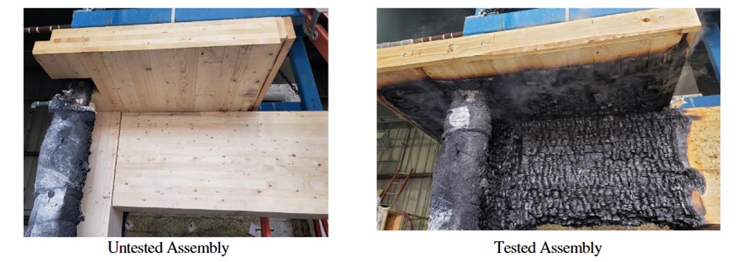
Between July 1 and July 10, 2020, Simpson Strong-Tie and SwRI conducted four separate fire tests of CBH hangers used to connect a glulam beam to a 16×16 glulam column.
Two of the tests involved single CBH assemblies — one tested for one hour and the other for two hours. The other two tests each involved multiple (4) CBH assemblies, again tested for one hour and for two hours. In all tests, the hangers were the CBH2.37 x 9.75 model, which is 2.37″ wide and 9.75″ in total height.
In all four cases, the members were routed and the connectors installed by Simpson Strong-Tie prior to shipment. After the application of a fire barrier (see next section), the connections were assembled at the testing site by Simpson Strong-Tie assisted by SwRI.
Details of the testing (continued) — application of a fire barrier
As remarked earlier, it’s imperative in concealed connections to minimize the gap between the beam and the column so as to prevent heat as much as possible from penetrating to the wood-metal interface.
As Arup explained in their summary of the testing, the char isn’t the only section of the timber that is compromised by fire — any exposure to thermal penetration weakens the wood’s load resistance:
Of particular importance is the reduction in timber strength with relatively small increases in timber temperature. It is recognized that once timber has reached 300°C the charring process is complete, and the timber has lost all of its strength. The mechanical properties of timber under heating are such that at 100°C, where the damage to timber becomes irreversible, the tensile strength has been reduced by 35% and the compressive strength by 75%. Thermal penetration depth for a temperature rise of 100°C is estimated as ranging from 15mm to 30mm depth behind the char layer, increasing as the fire duration increases.
Arup continues:
The most effective method to prevent an increased char at the interface is to use an intumescing fire sealant that will expand to seal the non-uniform interface gap. The fire sealant intumesces once it is exposed to temperatures in the order of 480°F to 570°F (250°C to 300°C). The sealant . . . can prevent hot gases moving into the interface gap for a period of time.
Prior to joining the plates in a connection, we routed a 1/2″-wide groove to install a strip of 3M Expantrol E-FIS intumescent fire sealant into the column face 1/2″ inside the beam’s edges, such that it would form a seal flush with the column’s surface.
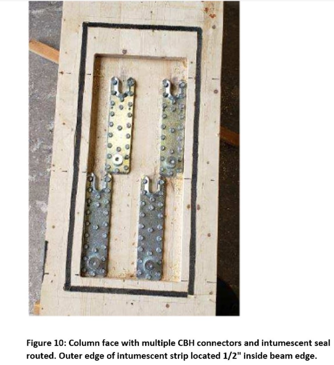
Substitutions for 3M Expantrol are allowable provided they meet or exceed the 3M Expantrol specifications for flame spread, smoke developed index, intumescent activation temperatures (expansion rate), and service temperatures.
Details of the testing (continued) — loading the beam
Once the beam was forklifted into place and connected to the column, a CLT floor was fastened with structural screws to the glulam beam. In this situation, the floor acts as a cover for the furnace, with fireproof walls extending above the furnace walls and enclosing the connection within the furnace and below the CLT floor for the duration of the test. The tested connection was loaded to represent actual building conditions by means of a loading jack located above the beam, which applied the maximum allowable service load directly to the CLT floor above the CBH connection.
The loading was based on Douglas fir–larch (DFL) construction, with the actual test specimens composed of spruce pine fir (SPF) by virtue of its easier and more economical availability. Because of the lower density (specific gravity) of the timber, SPF has a lower load capacity than DFL. Therefore, test results are applicable for both SPF and DFL and for assemblies of material with specific gravity between 0.42 and 0.50 or greater.
Details of the testing (continued) — turning up the heat
For each test, SwRI used a steel load frame that supported the base of the column on one end inside the furnace and the loaded beam on the other end outside the furnace. Four ASTM E119 furnace temperature probes gauged the furnace temperature. A computer-based data acquisition system captured the applied load, vertical displacement, and temperature measurements.
Details of the testing (continued) — results and assessment
The ASTM E119 test method is intended to evaluate the length of time for which a given assembly will contain a fire or retain its structural integrity — or both, depending on the type of assembly involved — during a predetermined fire exposure time.
According to the SwRI reports, all four assemblies achieved the specified endurance rating —whether 60 minutes or 120 minutes — while maintaining the required load when tested in general accordance with ASTM E119.
Arup concluded that the combined tests demonstrated the following facts about the CBH and its performance under fire:
- The connection can be assembled quickly.
- CBH connectors can resist high forces with only very small deflections and perform robustly even under heating.
- Recessing the connector so the beam-to-column interface leaves a minimal gap is very important.
- An intumescent seal is required to prevent the ingress of hot gases and increased charring at the beam-to-column interface.
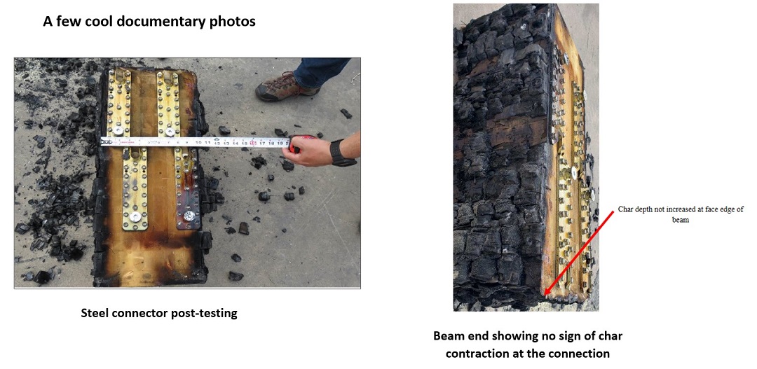
- In none of the fire tests carried out was there any indication of char-related contraction at the beam-to-column interface.
In their top-level summary:
The ASTM E119 fire tests for the CBH achieved both 1hr and 2hr fire resistance ratings. . . . The completed fire resistance tests and supporting SwRI reports allow engineers and architects to specify the Simpson Strong-Tie CBH connectors as a tested mass timber building component and satisfy the requirements of Section 703.2 of the IBC, for approval by an authority having jurisdiction (AHJ). [Boldfacing added.]
Everything considered, we’re quite pleased with how the CBH has performed under all industry-standard test conditions.
