Overcoming Adhesive Anchor Orientation Challenges with the Piston Plug Adhesive Delivery System

Modern code-listed adhesive anchors offer high-strength connection solutions for a variety of applications. However, as in all construction projects, good product performance requires proper selection and installation. In this blog post, we will discuss the challenge of installation orientation and an accessory that can help installers more easily make proper adhesive anchor installations—the piston plug adhesive delivery system.

ACI 318-19 Chapter 17 (Anchoring to Concrete) calculations use a uniform bond stress model to calculate an adhesive anchor’s resistance to bond failure. According to this theory, an adhesive anchor is assumed to transfer applied loads into the concrete base material uniformly along its effective embedment depth, hef. The equation for an anchor’s basic bond strength (expressed in pounds of force) is simply the adhesive formulation’s bond strength per unit area ( λaτcr ) multiplied by the idealized cylindrical surface area of the insert that is in contact with the adhesive ( πdahef ):

(ACI 318-19, Eq. (17.6.5.2.1))

oaa1
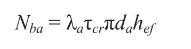
Although the model is a simplification of reality, the mathematical expression represents the core assumption that the adhesive is able to transfer stress completely along the entire depth of the anchorage. This is a key requirement in installation: Anchoring adhesives must be installed such that air entrapment and significant voids are prevented.

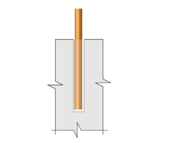
Downward installations (Figure 1) have historically presented relatively few challenges for adhesive injection in this regard. In such applications, gravity is helpful; the adhesive naturally flows to the bottom of the drilled hole while being dispensed from the cartridge through a static mixing nozzle. The installer maintains the open end of the nozzle below the free surface of the adhesive until the drilled hole is filled to the desired level. For deep holes, extension tubing is affixed to the open end of the nozzle to increase reach. This procedure avoids entrapping air bubbles in the adhesive material.

Figure 1 – Downward installation orientation

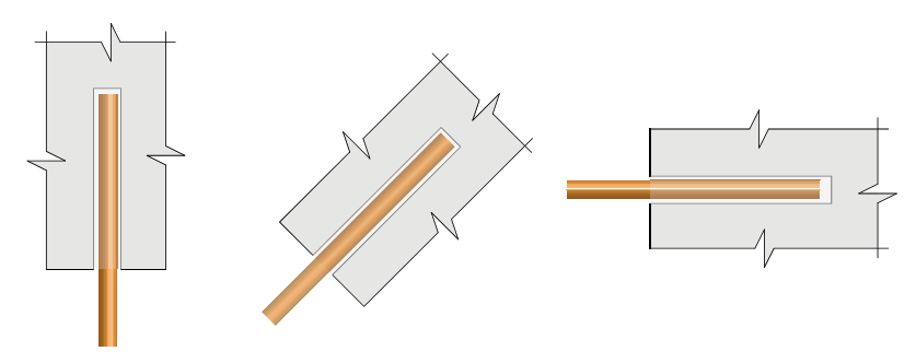
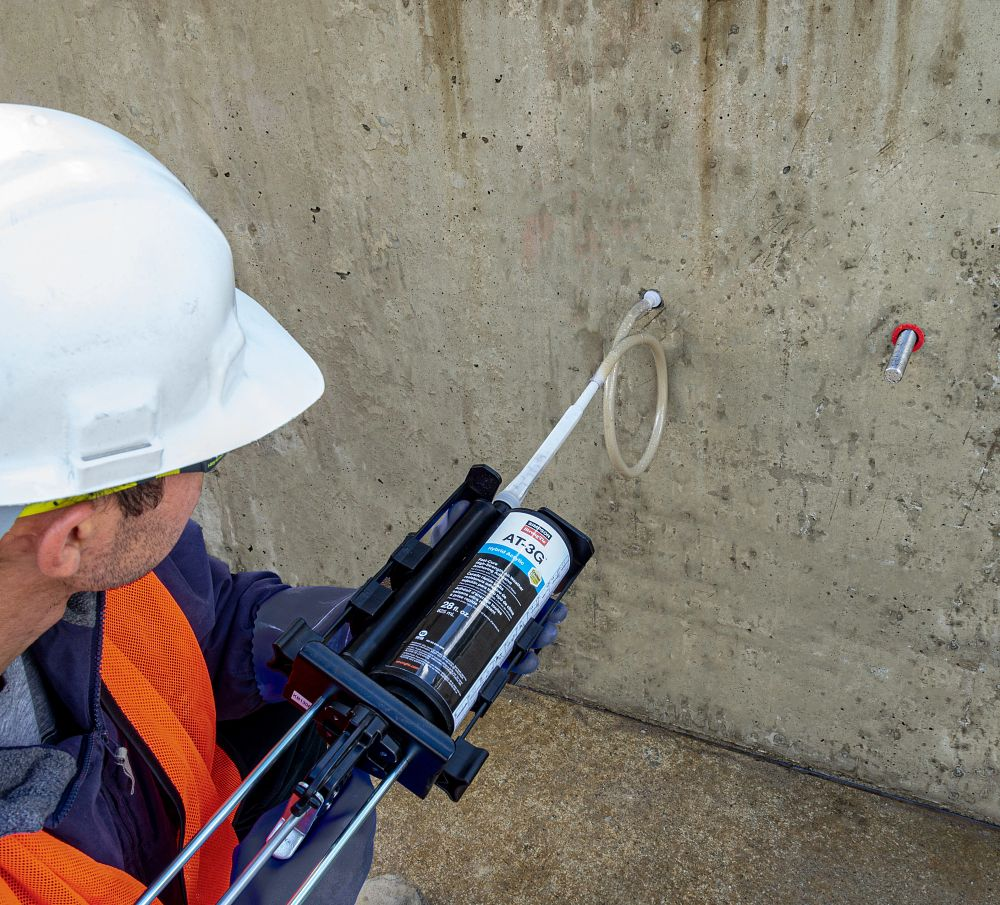
Installations into horizontal, upwardly inclined or overhead drilled holes (Figure 2) require more care on the part of adhesive anchor installers. Although the installation principle to avoid entrapping air is similar for these orientations, a key difference is that gravity does not help to keep the adhesive towards the “bottom” (deepest point) of the drilled hole. At worst, it can work against the installer when ambient temperatures may cause the adhesive to run out of the hole during injection. These adhesive anchor installations can be more difficult for an untrained installer and can slow the rate of work. This is one of the reasons that ACI 318-19 Section 26.13.3.2(e) requires continuous special inspection of adhesive anchor installations in these three orientations when the application is also intended to resist sustained loads.

Figure 2 – Overhead, upwardly inclined and horizontal installation orientations (Source: ACI 318-19, Fig. R2.2)
Figure 2 – Overhead, upwardly inclined and horizontal installation orientations (Source: ACI 318-19, Fig. R2.2)

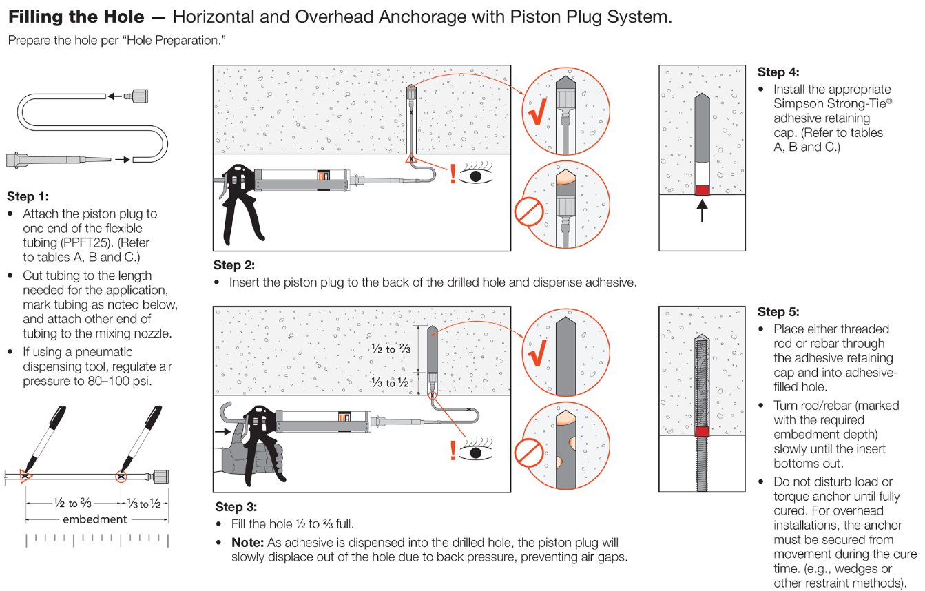
To aid the installer, Simpson Strong-Tie offers a piston plug adhesive delivery system (Figure 3). Consisting of pre-packaged flexible tubing, piston plugs and an adhesive retaining cap, this system allows installers to more easily and consistently make high-quality installations while completing their work efficiently. The installation sequence is provided in Figure 4.

Figure 3 – Piston plug delivery system

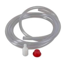
The system consists of three components:

  • Piston plug – The key component of the system, it is slightly smaller in diameter than the drilled hole. As the adhesive is dispensed into the drilled hole, the piston plug is displaced out of the hole by the advancing volume of the injected adhesive. The displacement creates a more positive feel for the installer to know where the free surface of the adhesive is.


  • Flexible tubing – For use with the piston plug to facilitate injection at the deepest point of the drilled hole.
  • Adhesive retaining cap – Provided to prevent adhesive material from flowing out of the drilled hole after dispensing and to provide a centering mechanism for the insert. For heavy inserts in overhead conditions, other means must be provided to carry the weight of the insert and prevent it from falling or becoming dislodged from the hole before the adhesive has fully cured.

Figure 4 – Installation sequence

What do you think about the piston plug adhesive delivery system? Let us know by posting a comment below.

Steel Strong-Wall® Footings Just got a Little Slimmer!

While 54 inches is a good height and will get you on most amusement park rides, what about this dimension for the width of a footing? We did some tests recently — actually a lot of tests — that answered that question.

Steel Strong-Wall® narrow panels are great for resisting high seismic or wind loads, but due to their narrow widths, their resulting anchor uplift forces can be rather hefty, requiring very large pad footings. How large? For Seismic Design Categories C-F, the largest cracked concrete solution per ACI318-11 Appendix D has a width of 54 inches and an effective embedment depth of 18 inches in order to ensure the anchor remains ductile. The overall length of this footing, as seen in Figure 1, can be up to 132 inches. While purely code driven, these solutions have historically presented challenges in the field. Most concrete contractors have to dig footings this size by hand. This often leads to discussions with their engineers about finding a better solution.

Figure 1: Slab-on-Grade Installation (Traditional Solution)

Simpson Strong-Tie has been studying cast-in-place anchorage extensively in recent years. Our research has been featured in a couple of blog posts: The Anchorage to Concrete Challenge – How Do You Meet It? and Podium Anchorage – Structure Magazine. Concrete podium slab anchorage was a multi-year test program that started with grant funding from the Structural Engineers Associations of Northern California for initial concept testing at Scientific Construction Laboratories Inc. and wrapped up with full-scale detailed testing completed at the Simpson Strong-Tie Tye Gilb Laboratory in Stockton, California. This joint venture studied the performance of anchorage reinforcement into thin podium deck slabs (10-14 inch) to resist the high overturning forces of continuous rod systems on 4-5-story mid-rise construction. The testing confirmed the need to comply with Appendix D requirements to prevent plastic hinging at anchor locations. Be on the lookout for an SE Blog post on that topic in the near future. Armed with what we learned, we decided to develop tested anchor reinforcing solutions for the Steel Strong-Wall.

The newly developed anchor reinforcement solutions for grade beams are calculated in accordance with ACI318 Appendix D and tested to validate performance. Anchor reinforcement isn’t a new concept, as it’s been in ACI318 for some time. Essentially, anchor reinforcements transfer load from the anchor bolt to the reinforcing, which restrains the breakout cone from occurring. For the new grade beam details, the additional ties near the anchor are designed to resist the load from the anchor and are developed into the grade beam. The new details offer solutions with widths as narrow as 18 inches when anchor reinforcement is used.

Two details have been developed: one for the larger panels (SSW18, SSW21, SSW24) as shown in Detail 1/SSW1.1, and one for the smaller panels (SSW12, SSW15) as shown in Detail 2/SSW1.1. The difference between the two is the number of anchor reinforcement ties specified in Detail 3/SSW1.1. For SSW18, SSW21 and SSW24 panels (Detail 1/SSW1.1), the total number of reinforcement per anchor is specified. Due to their smaller sizes, the anchor reinforcement ties specified in Detail 2/SSW1.1 for the SSW12 and SSW15 panels are the total required per panel.

Detail 1/SSW1.1
Detail 1/SSW1.1
Detail 2/SSW1.1
Detail 2/SSW1.1
Detail 3/SSW1.1
Detail 3/SSW1.1

Validation Testing

From the concrete podium deck anchorage test program, we discovered that the flexural and shear capacity of the slab is critical to anchor performance and must be designed to exceed the demands created by the attached structure. For grade beams, this also holds true. In wind-load applications, this demand includes the factored demand from the Steel Strong-Wall. In seismic applications, our testing and analysis showed that achieving the anchor performance expected by Appendix D design methodologies requires the concrete member design strength to resist the amplified anchor design demand from Appendix D Section D.3.3.4.3.

Validation testing was conducted to evaluate this concept. The test program consisted of a number of specimens with different configurations, including:

  • Closed tie anchor reinforcement
  • Non-closed tie u-stirrup anchor reinforcement
  • Control specimen without anchor reinforcement

Flexural and shear reinforcement were designed to resist Appendix D amplified anchorage forces and were compared to test beams designed for non-amplified strength level forces. The results of the testing are shown in Figure 2. In the higher Seismic Design Categories (C-F), the anchor assembly must be designed to satisfy Section D.3.3.4.3 in ACI318-11 Appendix D. In accordance with D.3.3.4.3 (a), the concrete breakout strength needs to be greater than 1.2 times the nominal steel strength of the anchor, 1.2NSA. This requires a concrete breakout strength of 87 kips for a Steel Strong-Wall that uses a 1-inch high-strength anchor.

Figure 2: Steel Strong-Wall Grade Beam Testing

Grade beams without the anchor reinforcement detail and with flexural and shear reinforcement designed to the Appendix D amplified anchorage forces performed similar to those with closed-tie anchor reinforcement and flexural and shear reinforcements designed to the non-amplified strength level forces. Both, however, came up short of the necessary forces required by Section D.3.3.4.3 (a). From Test V852, we discovered that even though the flexural and shear reinforcement were designed with the amplified forces, the non-closed tie u-stirrups did not ensure the intended performance. From observation, the u-stirrups do not provide adequate confinement of the concrete and tend to open up under loading conditions, resulting in splitting of the beam at the top as can be seen in the photo.

Test V852: Non-Closed U-Stirrups

Tests W785 and W841 resulted in the best performance. Both test specimens contained flexural and shear reinforcement designed for the amplified forces, as well as closed-ties. Two configurations were tested to study their performance — two piece closed-tie anchor reinforcement in W785 and a single piece closed-tie anchor reinforcement in Test W841. As seen in Figure 2, their performance was very similar, and met the requirements of Section D.3.3.4.3 (a). The closed-ties helped confine the concrete near the top of the beam, allowing the assembly to reach the expected performance load (See the photo below). It’s important to indicate the following specifics in the New Grade Beam Anchor Reinforcement Details:

  • Anchor Reinforcement is #4 closed-ties
  • SSWAB embedment depth is 16″ +/- ½” (as shown in Detail 3/SSW1.1). This is to ensure there is enough development length of the anchor reinforcement on both sides of the theoretical breakout surface as required by ACI318-11 D.5.2.9.
  • The minimum distances from the anchor bolt plate washer to top and bottom of closed tie reinforcement are 13 inches and 5 inches respectively to ensure proper development above and below the concrete breakout cone (refer to Detail 3/SSW1.1).
  • The spacing between the two vertical legs of the anchor reinforcement tie must be 10 inches apart. While this may differ from your shear reinforcement elsewhere in the grade beam, it ensures the reinforcement is located close enough to the anchor and adequate development length is provided.
  • Flexural reinforcement (top and bottom) and shear reinforcement (ties throughout the grade beam length) are per the designer. Simpson Strong-Tie has provided information in Detail 3/SSW1.1 for the applicable minimum LRFD Applied Design Seismic Moment (See Figure 3) to make sure the grade beam design will at least resist the applied anchor forces. Project design loads not related to the Strong-Wall panel also should be considered and could control the grade beam design.
Closed-Tie Anchor Reinforcement
Figure 3: LRFD Applied Design Seismic Moment

Simpson Strong-Tie is interested in hearing your thoughts on the new details. What is your opinion? How have the new details been received on your job sites?