Have you ever specified an adhesive for an unreinforced masonry (URM) retrofit? If so, you may have wondered about the difficulty of drilling holes at 22.5° from horizontal in order to properly install an anchor to take tension loads.
Category: Adhesives
Whether you need high-volume dispensing tools and bolts for rebar doweling on a high-traffic infrastructure retrofit project or a concrete adhesive for a do-it-yourself project, Simpson Strong-Tie offers a wide variety of adhesive anchoring products to meet virtually any need.
Our strong, versatile epoxy adhesives for concrete and brick are ideal for anchoring threaded rod, rebar and smooth dowels in an assortment of base materials. And our acrylic formulations deliver consistent performance for high-strength anchor grouting in a wide range of weather conditions — curing fast even in water-saturated concrete.
Allowable Load Tables at Your Service — A Look at the Technical Engineering Bulletin (TEB) for Anchors
One interesting part of being a field engineer for Simpson Strong-Tie is having the opportunity to see how different structural engineers may take different approaches to similar designs. We at Simpson Strong-Tie have come to appreciate these different approaches and embrace this phenomenon by providing multiple resources to aid in the completion of a design. This is very apparent when it comes to the design of post-installed anchors.
Overview of the Strength-Based Cracked and Uncracked Masonry Design Standards for Adhesive Anchors
We’re entering the year 2024 — welcome to the world of cracked and uncracked masonry. The last time Simpson Strong-Tie wrote a blog post regarding design criteria for post-installed anchors in masonry was in 2019, and ICC-ES was considering the adoption of a revised version of AC58, the Acceptance Criteria for Adhesive Anchors in Cracked and Uncracked Masonry Elements. Acceptance Criteria, or ACs, outline the testing that a manufacturer must comply with in order to get an evaluation report. In some cases, the ACs contain calculations methods if they are otherwise unavailable. If you missed the previous blog post, here is a link so you can explore a bit of the history that has led us to where we are today.
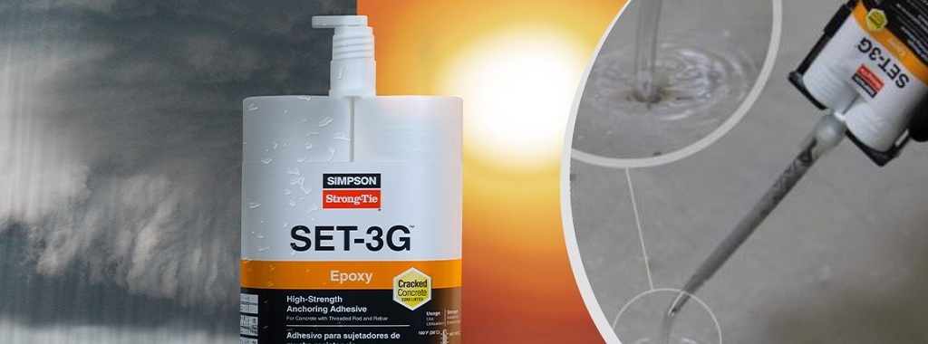
Dry, Soaked, or Submerged Concrete — SET-3G Adhesive Allows Anchoring in Any Condition
Modern construction schedules and conditions create a demand for solutions that can perform in a wide variety of environments. In the following post, Field Engineer Chris Johnson provides a rundown of different concrete and hole conditions for adhesive anchoring, the related design factors, and proper installation instructions and approved adhesive products for submerged anchorage.
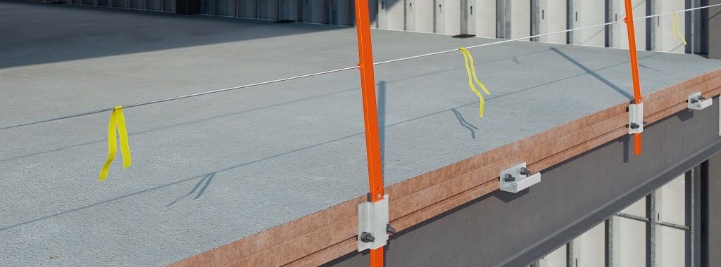
Learn New Design Methods to Enclose Buildings Faster Webinar Q&A
In this post, we follow up on our October webinar, New Design Methods to Enclose Buildings Faster, by answering some of the interesting questions raised by attendees.
During the webinar, we discussed new design methods and solutions for curtain-wall and cladding connections and how they can maximize efficiency and resiliency throughout the construction process. In case you could not join our discussion, you can watch the on-demand webinar and earn PDH and CEU credits here.Continue Reading
How Should I Determine a Tension Test Load? Guidelines on Proof Loading Adhesive Anchors
Have you ever been involved on a project where a post-installed anchor failed when loaded? What was the circumstance? Was the anchor installed with incorrect torque or was the hole improperly cleaned, resulting in lower capacities than published? Unfortunately, in the world of concrete anchors, installations are sometimes incorrect as a result of not following instructions. Alternatively, perhaps you’re working on a project where special inspection wasn’t performed as required by the building code. What should be done in these cases?
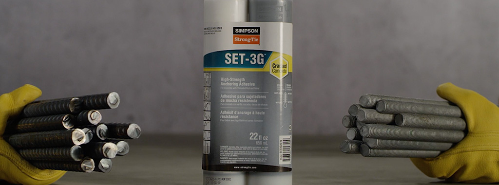
Epoxy vs. Acrylic Adhesive Systems: Which Is Right for Me?
Not all anchoring adhesives are created equal. There are important differences between acrylic-based and epoxy-based adhesive systems — differences that affect installation, gel and cure times, and anchoring performance. In the following post, Marlou Rodriguez, S.E., of Simpson Strong-Tie, lays out some of the comparative installation advantages of each system.
There are two common types of adhesives for anchoring threaded rod or rebar into concrete — epoxy-based systems and acrylic-based systems. What’s the difference? When should you specify one rather than the other? This blog post will help you understand the differences and guide you in choosing the best adhesive for your anchoring solution.
Continue Reading
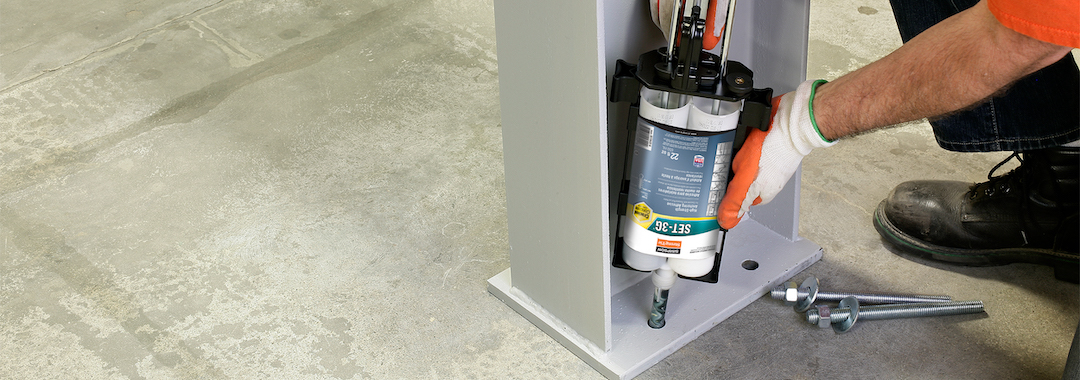
Simpson Strong-Tie® SET-3G™ Adhesive Offers a Ductile Solution for Post-Installed Anchorage near a Concrete Edge
Designing post-installed anchorage near a concrete edge is challenging, especially since the ACI provisions for cracked-concrete anchorage went into effect. In the following post, one of our field engineers, Jason Oakley, P.E., explains how SET-3G™ and Anchor Designer™ for Concrete software from Simpson Strong-Tie make it easier to design a ductile anchor solution.
Engineers often provide holdown anchoring solutions near a concrete edge to help prevent overturning of light-frame shear walls during a seismic (or high-wind) event. Sometimes a post-installed anchor must be used if the cast-in-place anchor was mislocated or misinstalled, or is located where a retrofit or addition is needed. Since the cracked-concrete anchorage design provisions went into effect more than a decade ago, it has been challenging for engineers to offer a near-edge post-installed anchoring solution. This is especially true for structures subject to earthquake loads in seismic design category (SDC) C through F. Simpson Strong-Tie’s new SET-3G epoxy is the first anchoring adhesive in the industry to offer exceptionally high bond-strength values that permit ductile anchorage in concrete near an edge. This blog post will cover a specific example that focuses on Chapter 17 of ACI 318-19 to design a threaded rod, anchored with SET-3G adhesive, used to secure a holdown located 1 3/4″ away from a single concrete edge (Figure 1).
Continue Reading

Considerations for Designing Anchorage in Proximity to Abandoned Anchor Holes
 This week’s post comes from Dan Harmon, an R&D engineer for Simpson Strong-Tie’s Infrastructure-Commercial-Industrial (ICI) group. Dan specializes in post-installed concrete anchor design and spent a decade managing Simpson’s anchor testing lab, where he developed extensive knowledge of anchor behavior and performance. He has a Bachelor of Science in mechanical engineering from the University of Illinois Urbana-Champaign.
Designers and engineers can spend hundreds of hours on detailed drawings of structures, but there are often conditions and coordination that can change well-planned details and drawings. As we all know, paper and reality don’t always agree. Anchorage locations can move as a result of unforeseen circumstances such as encountering reinforcing bars in an existing concrete slab or interference between different utility trades.
With post-installed anchors, one particular jobsite change may require abandoning a hole that has been drilled, leaving the final anchor location adjacent to the abandoned hole. When a hole for an anchor is drilled but never used, it essentially creates a large void in the concrete. Depending on where this void is located in relation to an installed anchor, there is potential for the capacity of that anchor to be reduced. To give guidance on this situation to specifiers, users and contractors, Simpson Strong-Tie conducted a large series of tests in their ISO 17025–accredited Anchor Systems Test Lab in Addison, Illinois.
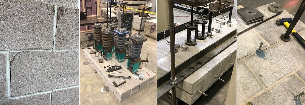
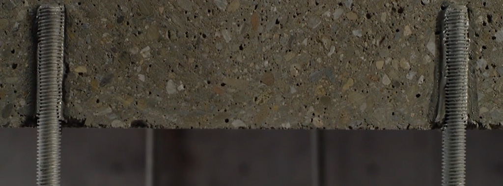
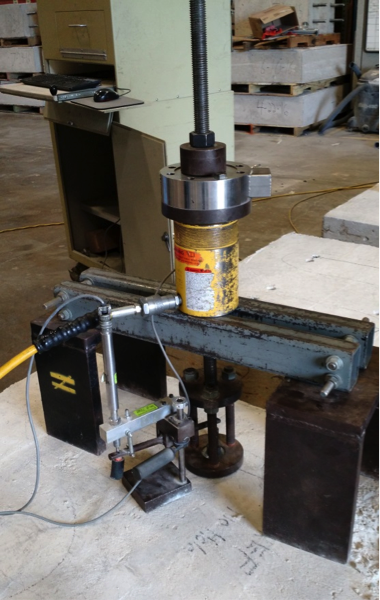
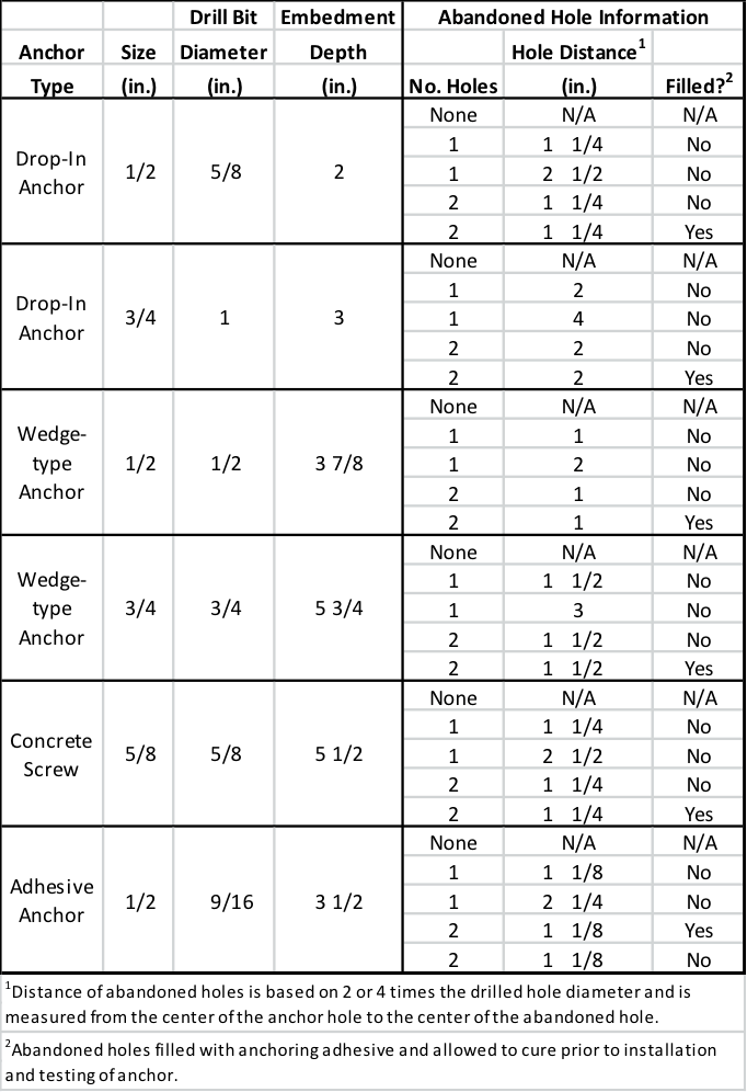
To evaluate the effect of abandoned holes located adjacent to post-installed anchors, we performed tension tests meeting the requirements of ASTM E488-15 (see Figure 1). A variety of anchor types with common diameters were tested:
- Drop-in anchors (1/2″ and 3/4″ diameter)
- Wedge-type anchors (1/2″ and 3/4″ diameter)
- Concrete screws (1/2″ diameter)
- Adhesive anchors with threaded rod (1/2″ diameter)
Each anchor type and diameter was tested under five different conditions:
- No abandoned hole near the installed anchor. This is considered the reference condition to which other tests are to be compared.
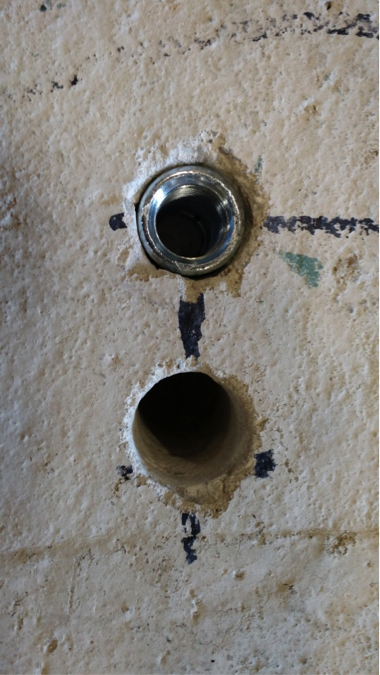
- One abandoned hole at a distance of two times the hole diameter (2d) away from the installed anchor. See Figure 2.
- One abandoned hole at a distance of four times the hole diameter (4d) away from the installed anchor.
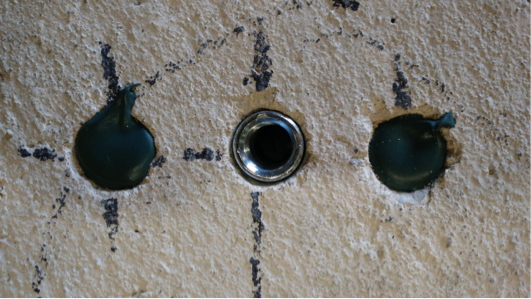
- Two abandoned holes, each at a distance of two times the hole diameter (2d) away from the installed anchor. In test conditions with two holes, the holes were located on either side of the installed anchor, approximately 180º from each other. See Figure 3.
- Two abandoned holes, each at a distance of two times the hole diameter (2d) away from the installed anchor, with the holes refilled with a concrete anchoring adhesive that was allowed to cure fully prior to testing. See Figure 4.

This test program is summarized in Table 1. In all cases, the abandoned hole was of the same diameter and depth as the hole prescribed for the installed anchor.
Five tests for each anchor under each condition were tested, and the mean and coefficient of variance of each data set were calculated. These calculated values were used to compare the different conditions.
Across the different anchor types and diameters, the test results showed a number of general rules that held true.
Summary Results
Abandoned holes that are 2” or more away from the anchor have little to no effect on the tension performance of the anchor. Compared to the reference condition with no abandoned hole near the anchor, conditions where the abandoned hole was sufficiently far away were found to be essentially equivalent. This equivalence held true even for anchor types that create expansion forces (drop-in and wedge-type anchors) during their installation.
Two abandoned holes have the same effect on performances as one, regardless of distance from the anchor. This testing showed that adding a second abandoned hole near an installed anchor did not adversely affect tension performance in a significant way. Even within distances of 2 inches, performance did not drop substantially – if at all – in conditions involving two abandoned holes as compared to one.
Filling abandoned holes with an anchoring adhesive prior to installation of the anchor improves performance. In all cases tested, filling abandoned holes with adhesives resulted in increased performance compared to leaving the holes empty. In a majority of cases, performance with filled holes was equivalent to performance in the reference condition regardless of the distance from the anchor.
When the abandoned hole is more than two times the drilled hole diameter but less than 2″from the anchor – and left unfilled – the testing showed a loss in performance. Not surprisingly, the degree of that loss was dependent on the type of anchor. Table 2 shows the capacity reduction compared to the reference condition in testing with expansion anchors. Table 3 shows the same results for concrete screws and adhesive anchors. Conservative suggested performance reductions in these conditions would be 20% for expansion anchors and 10% for concrete screws and adhesive anchors.


In an ideal world, the engineer’s designs could be followed at all times at the jobsite. But we don’t live in an ideal world. Good engineering judgment is needed in situations where variation is required, and having data to support those decisions is always helpful. In the case of abandoned holes near post-installed anchors, it’s Simpson Strong-Tie’s hope that this testing provides additional guidance for the designer, inspector, and jobsite worker.

Concrete Anchor Design for the International Building Code: Part 3
Specification of Concrete Anchors
The 2024 IBC and its Referenced Standard, ACI 318-19, is the first to mandate that contract documents specifically address installation, inspections and design parameters of concrete anchorage. For this reason, the specification of anchors in drawing details alone is impractical. To fully and effectively address these code mandates, concrete anchorage is more practically specified in both drawing detail(s) and the General Structural Notes or specifications of the contract documents. The drawing detail(s) would typically call out the anchor type, material specification, diameter, and embedment depth. The General Structural Notes or specifications would include the name of the qualified anchor(s) and address the installation, inspections and design parameter requirements of ACI 318-19.
The following provisions of ACI 318-19 Chapter 26 discuss the contract document requirements for concrete anchorage. Section 26.7.2 establishes compliance requirements for anchor installation, including proper positioning of cast-in anchors, consolidation of concrete around anchors, and installation of post-installed anchors in accordance with the Manufacturer’s Printed Installation Instructions (MPII). Section 26.7.2 further requires that post-installed anchors be installed by qualified installers, and that adhesive anchors installed in horizontal or upwardly inclined orientations to resist sustained tensile loads be installed by certified installers. Minimum concrete age requirements for adhesive anchors are also addressed.
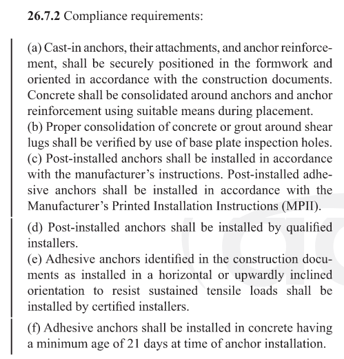
The commentaries to Section 26.7.2, R26.7.2 (c)(e)(f) emphasize the sensitivity of anchor performance to proper installation and reinforces the importance of qualified personnel and strict compliance with MPII for post-installed anchors. Simpson Strong-Tie Co. Inc. provides free installer training conducted by experienced Technical Sales Representatives for adhesive, mechanical, and specialty anchors. For additional information regarding installer training opportunities, contact 1-800-999-5099.
Additional requirements related to inspection, installer qualification, and testing of adhesive anchors – including special inspection and proof loading where required – are addressed in ACI 318-19 Sections 26.7.1 and 26.7.2, as well as through the applicable inspection provisions of the general building code.
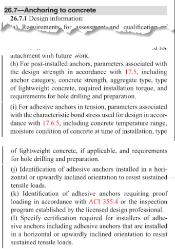
Per the section above, anchor installation requires inspection per ACI 318-19 Section 26.7.2. In addition, the design parameters for adhesive anchors are required to be specified in the contract documents. An explanation of the design parameters listed in ACI 318-19 Section 26.7.1 is provided below:
- Proof loading where required in accordance with ACI 355.4. Proof loading is only required for adhesive anchors loaded in tension in which the inspection level chosen for the adhesive anchor design is “Continuous” (Ref. ACI 355.4 Section 10.4.6). Selecting “Continuous Inspection” can result in a higher “Anchor Category,” which in turn results in a higher strength reduction factor, φ. Reference Section 13.3.4 of ACI 355.4 for the minimum requirements of the proof loading program, where required. The Design Professional is responsible for performing the quantity, the duration of the applied load, and the proof load to which the anchors will be tested. These parameters will be specific to the anchor design conditions.
- Minimum age of concrete at time of anchor installation. Per ACI 318-19 Section 26.7.2(f), adhesive anchors must be installed in concrete having a minimum age of 21 days at time of anchor installation unless otherwise permitted by the applicable evaluation report. Design professionals should refer to current manufacturer evaluation reports and published technical data for any product-specific allowances, limitations, or installation requirements.
- Concrete temperature range. This is the in-service temperature of the concrete into which the adhesive anchor is installed. Temperature Ranges are categorized as 1, 2 or 3. Some manufacturers use A, B, or C as the category designations. Each Temperature Range category has a maximum short-term concrete temperature and a maximum long-term concrete temperature. Short-term concrete temperatures are those that occur over short intervals (diurnal cycling). Long-term concrete temperatures are constant temperatures over a significant time period.
- Moisture condition of concrete at time of installation. Moisture conditions, as designated by ACI 355.4, are “dry,” or “water-saturated.” Moisture condition impacts the characteristic bond stress of an adhesive.
- Type of lightweight concrete, if applicable.
- Requirements for hole drilling and preparation. These requirements are specific to the adhesive, and are described in the Manufacturer’s Printed Installation Instructions (MPII). Reference to the MPII in the contract documents is sufficient.
Adhesive anchors installed in a horizontal or upwardly inclined orientation that resist sustained tension loads require a “certified” installer according to ACI 318-19 Section 26.7.1(l).
According to the commentary to Section 26.7.1, R26.7.1(l), certification may also be appropriate for other safety-related applications. Installers can become certified through testing and training programs that include written and performance examinations as defined by the ACI Adhesive Anchor Installer Certification program (ACI CPP 680.1-17) or similar programs with equivalent requirements. The acceptability of certification other than the ACI Adhesive Anchor Installer Certification should be determined by the Licensed Design Professional. In addition, installers should obtain instruction through productspecific training offered by manufacturers of qualified adhesive anchor systems.
An equivalent certified installer program should test the adhesive anchor installer’s knowledge and skill by an objectively fair and unbiased administration and grading of a written and performance exam. Programs should reflect the knowledge and skill required to install available commercial anchor systems. The effectiveness of a written exam should be verified through statistical analysis of the questions and answers. An equivalent program should provide a responsive and accurate mechanism to verify credentials, which are renewed on a periodic basis.
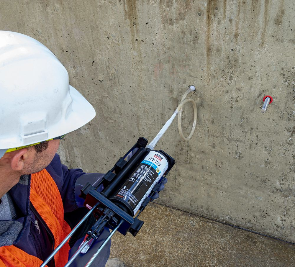
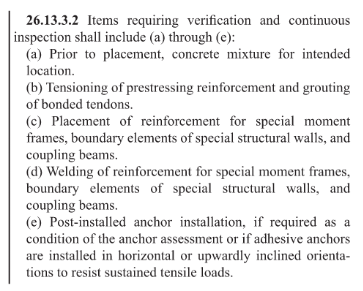
The installation of adhesive anchors in a horizontal or upwardly inclined orientation presents unique challenges to the installer. Simply put, the effects of gravity for these applications make it difficult to prevent air bubbles and voids, which can limit full adhesive coverage of the insert (threaded rod or reinforcing bar). Due to the increased installation difficulty of these anchors, they are required to be continuously inspected by a certified special inspector according to ACI 318-19 Section 26.13.3.2(e).
Suggested General Structural Notes or specifications for post-installed anchors can be viewed and downloaded at here, or contact a Simpson Strong-Tie® representative for help with your post-installed General Structural Notes or specifications.
Simpson Strong-Tie Suggested General Note for Anchor Products
Post-Installed Anchors into Concrete, Masonry and
Steel and Cast-in-Place Anchors into Concrete
The below products are the design basis for this project. Substitution requests for products other than those listed below may be submitted by the contractor to the Engineer-of-Record (EOR) for review. Substitutions will only be considered for products having a code Report recognizing the product for the appropriate application and project building code. Substitution requests shall include calculations that demonstrate the substituted product is capable of achieving the equivalent performance values of the
design basis product. Contractor shall contact manufacturer’s representative (800-999-5099) for product installation training and a letter shall be submitted to the EOR indicating training has taken place. Refer to the building code and/or evaluation report for special inspections and proof load requirements.
For anchoring into cracked and uncracked concrete
a) Mechanical anchors shall have been tested in accordance with ACI 355.2 and/or ICC-ES AC193 for cracked concrete and seismic applications. Pre-approved products include:
- Simpson Strong-Tie® Strong-Bolt® 2 (ICC-ES ESR-3037)
- Simpson Strong-Tie® Titen HD® (ICC-ES ESR-2713)
- Simpson Strong-Tie® Titen HD® Rod Hanger (ICC-ES ESR-2713)
b) Adhesive anchors shall have been tested in accordance with ACI 355.4 and/or ICC-ES
AC308 for cracked concrete and seismic applications. Adhesive anchors shall be installed
by a certified adhesive anchor installer where designated on the contract documents.
Pre-approved products include:
- Simpson Strong-Tie® AT-3G™ (ICC-ES ESR-5026)
- Simpson Strong-Tie® SET-3G™ (ICC-ES ESR-4057)
- Simpson Strong-Tie® ET-3G™ (ICC-ES ESR-5334)