This is Part 1A of a four-part series I’ll be doing on how connectors, fasteners, anchors and cold-formed steel systems are load rated.
I envisioned doing a four-part series on how connectors, fasteners, anchors, and cold-formed steel are load rated. After writing the first installment on connectors, I realized that connectors are a bit more complicated, since the testing and evaluation for joist hangers (or similar devices) is different than testing for holdown devices. And I wanted to discuss holdowns. So without belaboring the apology for my numbering system, this will be part 1A of the series – still discussing wood connectors, but focusing on holdowns and some of the unique requirements in their load rating.Continue Reading
This is Part 1A of a four-part series I’ll be doing on how connectors, fasteners, anchors and cold-formed steel systems are load rated.
I envisioned doing a four-part series on how connectors, fasteners, anchors, and cold-formed steel are load rated. After writing the first installment on connectors, I realized that connectors are a bit more complicated, since the testing and evaluation for joist hangers (or similar devices) is different than testing for holdown devices. And I wanted to discuss holdowns. So without belaboring the apology for my numbering system, this will be part 1A of the series – still discussing wood connectors, but focusing on holdowns and some of the unique requirements in their load rating.
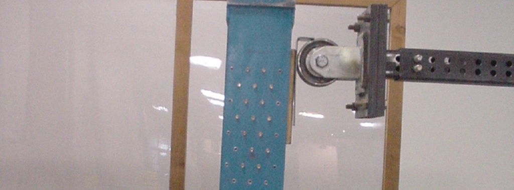
AC155, Acceptance Criteria for Hold-Downs (Tie-Downs) Attached to Wood Members, was first developed in 2005 to better address boundary conditions, deflection limits, and wood post limits. Prior to AC155, holdowns were evaluated based on testing on a steel jig with a safety factor of 3.0 and an NDS bolt calculation. Deflection at the allowable load was simply reported so that it was available for use in design, but there was not a deflection limit that affected the load rating. Bolted Holdown – Steel Jig Test
In the steel jig setup shown, the jig keeps the holdowns stationary while the rectangular bar underneath the holdowns is pushed downward to simulate an uplift force. This was (and still is) an effective method of testing the capacity of the steel body of a holdown, but it does not tell you a lot about the deflection of the holdown when installed on a wood member. Since story-drift is such a critical component to shearwall performance and the deflection of holdowns has a significant effect on the total drift, this needed to be address in the holdown test standard. Continue Reading
We use cookies on this site to enhance your user experience. By clicking "I AGREE" below, you are giving your consent for us to set cookies. Privacy PolicyI AGREE
Privacy & Cookies Policy
Privacy Overview
This website uses cookies to improve your experience while you navigate through the website. Out of these cookies, the cookies that are categorized as necessary are stored on your browser as they are essential for the working of basic functionalities of the website. We also use third-party cookies that help us analyze and understand how you use this website. These cookies will be stored in your browser only with your consent. You also have the option to opt-out of these cookies. But opting out of some of these cookies may have an effect on your browsing experience.
Necessary cookies are absolutely essential for the website to function properly. This category only includes cookies that ensures basic functionalities and security features of the website. These cookies do not store any personal information.
Any cookies that may not be particularly necessary for the website to function and is used specifically to collect user personal data via analytics, ads, other embedded contents are termed as non-necessary cookies. It is mandatory to procure user consent prior to running these cookies on your website.