Concrete Anchor Design for the International Building Code: Part 3

Specification of Concrete Anchors
The 2012 IBC and its Referenced Standard, ACI 318-11, is the first to mandate that contract documents specifically address installation, inspections and design parameters of concrete anchorage. For this reason, the specification of anchors in drawing details alone is impractical. To fully and effectively address these code mandates, concrete anchorage is more practically specified in both drawing detail(s) and the General
Structural Notes or specifications of the contract documents. The drawing detail(s) would typically call out the anchor type, material specification, diameter, and embedment depth. The General Structural Notes or specifications would include the name of the qualified anchor(s) and address the installation, inspections and design parameter requirements of ACI 318-11.


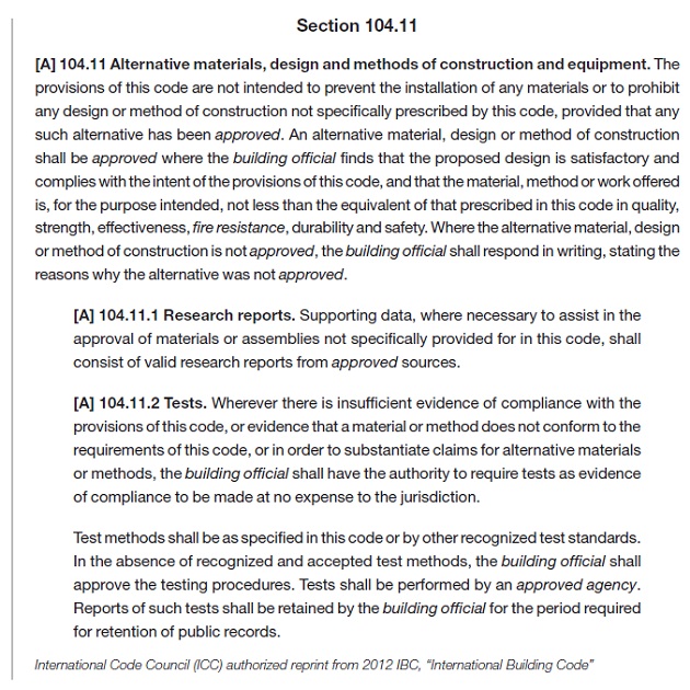
The following sections of ACI 318-11 discuss the contract document requirements for concrete anchorage:

cadp3.1

The commentary in ACI 318-11, RD.9.1 discusses the sensitivity of anchor performance to proper installation. It emphasizes the importance of qualified installers for all anchors, and compliance with the Manufacturer’s Printed Installation Instructions (MPII) for post-installed anchors. Training is required for adhesive anchor installers per ACI 318-11 D.9.1. Simpson Strong-Tie Co. Inc. provides free installer training by experienced Technical Sales Representatives for our adhesive, mechanical and specialty anchors. Contact us at 1-800-999-5099. Special inspection and proof loading are addressed in ACI 318-11 D.9.2
and D.9.2.1.

cadp3.2

Per the section above, anchor installation requires inspection per Section D.9.2. In addition, the design parameters for adhesive anchors are required to be specified in the contract documents. An explanation of the design parameters listed in ACI 318-11 D.9.2.1 is provided below:

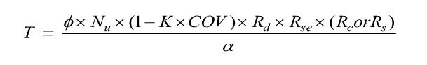
  1. Proof loading where required in accordance with ACI 355.4. Proof loading is only required for adhesive anchors loaded in tension in which the inspection level chosen for the adhesive anchor design is “Continuous” (Ref. ACI 355.4 Section 10.4.6). Selecting “Continuous Inspection” can result in a higher “Anchor Category,” which in turn results in a higher strength reduction factor, φ. Reference Section 13.3.4 of ACI 355.4 for the minimum requirements of the proof loading program, where required. The Design Professional is responsible for performing the quantity, the duration of
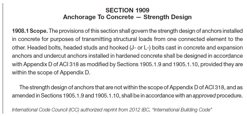
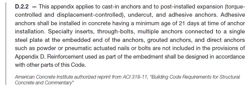
    the applied load, and the proof load to which the anchors will be tested. These parameters will be specific to the anchor design conditions.
  2. Minimum age of concrete at time of anchor installation. Per ACI 318 D.2.2, adhesive anchors must be installed in concrete having a minimum age of 21 days at time of anchor installation. Simpson Strong-Tie® has performed in-house testing of SET-XP®, AT-XP®, and ET-HP® adhesive anchors installed in 7-day- and 14-day-old concrete. The results of testing are published in an engineering letter (L-A-ADHGRNCON15.pdf), which can be viewed and downloaded at www.strongtie.com.
  3. Concrete temperature range. This is the in-service temperature of the concrete into which the adhesive anchor is installed. Temperature Ranges are categorized as 1, 2 or 3. Some manufacturers use A, B, or C as the category designations. Each Temperature Range category has a maximum short-term concrete temperature and a maximum long-term concrete temperature. Short-term concrete temperatures are those that occur over short intervals (diurnal cycling). Long-term concrete temperatures are constant temperatures over a significant time period.
  4. Moisture condition of concrete at time of installation. Moisture conditions, as designated by ACI 355.4, are “dry,” or “water-saturated.” Moisture condition impacts the characteristic bond stress of an adhesive.
  5. Type of lightweight concrete, if applicable.
  6. Requirements for hole drilling and preparation. These requirements are specific to the adhesive, and are described in the Manufacturer’s Printed Installation Instructions (MPII). Reference to the MPII in the contract documents is sufficient.


Adhesive anchors installed in a horizontal or upwardly inclined orientation that resist sustained tension loads require a “certified” installer.

cadp3.3

cadp3.4

A certification program has been established by ACI/CRSI. Installers can obtain certification by successful completion of this program. Contact your local ACI or CRSI chapter for more information. Other means of certification are permitted, and are the responsibility of the licensed design professional.

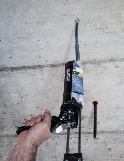
The installation of adhesive anchors in a horizontal or upwardly inclined orientation presents unique challenges to the installer. Simply put, the effects of gravity for these applications make it difficult to prevent air bubbles and voids, which can limit full adhesive coverage of the insert (threaded rod or reinforcing bar). Due to the increased installation difficulty of these anchors, they are required to be continuously inspected by a certified special inspector.

cadp3.5

Suggested General Structural Notes or specifications for post-installed anchors can be viewed and downloaded at here, or contact a Simpson Strong-Tie® representative for help with your post-installed General Structural Notes or specifications.

Simpson Strong-Tie Suggested General Note for Anchor Products

Post-Installed Anchors into Concrete, Masonry and
Steel and Cast-in-Place Anchors into Concrete

The below products are the design basis for this project. Substitution requests for products other than those listed below may be submitted by the contractor to the Engineer-of-Record (EOR) for review. Substitutions will only be considered for products having a code Report recognizing the product for the appropriate application and project building code. Substitution requests shall include calculations that demonstrate the substituted product is capable of achieving the equivalent performance values of the
design basis product. Contractor shall contact manufacturer’s representative (800-999-5099) for product installation training and a letter shall be submitted to the EOR indicating training has taken place. Refer to the building code and/or evaluation report for special inspections and proof load requirements.

  1. For anchoring into cracked and uncracked concrete

a) Mechanical anchors shall have been tested in accordance with ACI 355.2 and/or ICC-ES AC193 for cracked concrete and seismic applications. Pre-approved products include:
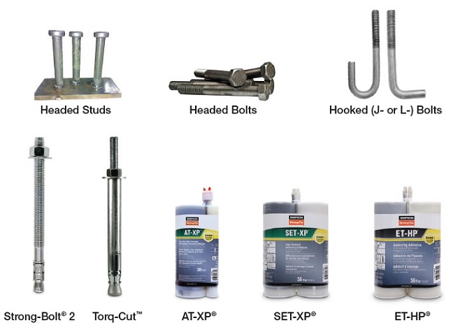
i. Simpson Strong-Tie® Strong-Bolt® 2 (ICC-ES ESR-3037)
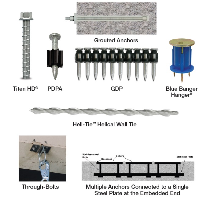
ii. Simpson Strong-Tie® Titen HD® (ICC-ES ESR-2713)
iii. Simpson Strong-Tie® Torq-Cut® (ICC-ES ESR-2705)
iv. Simpson Strong-Tie® Titen HD® Rod Hanger (ICC-ES ESR-2713)
v. Simpson Strong-Tie® Blue Banger Hanger® (ICC-ES ESR-3707, except roof deck insert)

b) Adhesive anchors shall have been tested in accordance with ACI 355.4 and/or ICC-ES
AC308 for cracked concrete and seismic applications. Adhesive anchors shall be installed
by a certified adhesive anchor installer where designated on the contract documents.
Pre-approved products include:
i. Simpson Strong-Tie® AT-XP® (IAPMO-UES ER-263)
ii. Simpson Strong-Tie® SET-XP® (ICC-ES ESR-2508)
III. Simpson Strong-Tie® ET-HP® (ICC-ES ESR-3372)

cadp3.6

Concrete Anchor Design for the International Building Code: Part 2

Designing “Alternative Materials”
Concrete anchor types whose designs are not addressed in the IBC or its Referenced Standards, or are specifically excluded from the scope of the Referenced Standard (ACI 318-11), may be recognized as Alternative Materials. Section 1909 of the 2012 IBC requires that “The strength design of anchors that are not within the scope of Appendix D of ACI 318, shall be in accordance with an approved procedure.” Section D.2.2 of ACI 318-11 lists some concrete anchor types that are considered “Alternative Materials” and specifically excludes these anchors from its scope. The list of “Alternative Material” anchors provided in this section is not, however, a comprehensive list.

Section 104.11 of the 2012 IBC describes how the design professional must approach the design of Alternative Materials.

cadp2.1

Section 104.11 provides the design professional with two options for the substantiation of the acceptable performance of an Alternative Material:

a.
Research Reports. As described in the previous section (Design of Code Anchors), Research Reports are referenced as the primary source for the design and qualification of Alternative Materials. Research Reports for anchors are published by IAPMO UES or ICC-ES, both ANSI ISO 17065 accredited agencies. Publicly developed, majority-approved acceptance criteria are used to establish the test program and minimum performance requirements for an anchor type. Some Alternative Material anchor types have established acceptance criteria to which a product can be evaluated:

  • Screw Anchors in Concrete (such as Simpson Strong-Tie® Titen HD®): ICC-ES AC193
  • Headed Cast-in Specialty Inserts (such as Simpson Strong-Tie® Blue Banger Hanger®): ICC-ES AC446
  • Powder- or Gas-Actuated Fasteners (such as Simpson Strong-Tie® PDPA and GDP): ICC-ES AC70

If Research Reports are used to substantiate an anchor’s performance, the design professional is bound by the design methodology and product limitations described in the Research Report.

b.
Tests. If a Research Report is not available, and no acceptance criteria exists for a given anchor type, IBC Section 104.11 permits the use of tests performed in accordance with “recognized and accepted test methods” by an “approved agency” to substantiate performance. One example of an anchor type for which no acceptance criteria exists is:

  • Helical Wall Ties (such as Simpson Strong-Tie® Heli-Tie™)

Cracked Concrete Determination
One of the many design considerations that the design professional must determine when designing either “Code Anchors” or anchors qualified as “Alternative Materials” is whether to consider the state of the concrete “cracked” or “uncracked.” The concrete state can significantly influence the anchor’s capacity. Neither the IBC nor ACI 318, Appendix D explicitly defines which applications should be categorized as “cracked” or “uncracked” concrete. The design professional must determine by analysis whether cracking will occur in the region of the concrete member where the anchors are installed. Absent an analysis to determine whether cracking will occur, the design professional may conservatively assume that the concrete state is “cracked.” With that said, there are two circumstances that require the design professional to design for “cracked” concrete:

a) Anchors in structures assigned to Seismic Design Categories C, D, E, or F (per 2012 IBC, Chapter 16) are required to be designed for “cracked” concrete unless the design professional can demonstrate that cracking does not occur at the anchor locations. The prequalification requirements of ACI 355.2 for mechanical anchors and ACI 355.4 for adhesive anchors include a test program that evaluates the performance of anchors in cracked concrete. Only anchors that have been tested and have passed the cracked concrete test program qualify for use in “cracked” concrete. The Research Report for a post-installed anchor (mechanical or adhesive) will clearly indicate whether it qualifies for use in “cracked concrete.”
b) Anchors located in a region of the concrete element where analysis indicates cracking at service level loading must be designed for “cracked” concrete (e.g. fr ≥ 7.5λ√f’c, ACI 318-11 eq. 9-10).

The design professional must consider additional factors that have the potential to result in concrete cracking in the region of anchorage. These factors include restrained shrinkage, temperature changes, soil pressure, and differential settlement. If no cracking is assumed in the region of the anchorage, the design professional should be able to justify that assumption.

Design Calculations

The design methodology in ACI 318 Appendix D is cumbersome. Calculations can be performed by hand using the design equations in Appendix D, inserting the substantiated data from an anchor manufacturer’s data tables or Research Reports to design with post-installed anchors. Designing with cast-in-place “Code Anchors” does not require additional data beyond what is included in ACI 318, Appendix D since these are “standard” anchors with standard design characteristics.

Performing hand calculations can be time-consuming, and for most design professionals is impractical due to the complexity of the design equations associated with multiple failure modes required to be considered. Design software, such as Simpson Strong-Tie® Anchor Designer™ Software for ACI 318, ETAG and CSA provides a fast, reliable method of calculating anchor performance for both cast-in-place and post-installed anchors. This software designs both “Code Anchors” and “Alternative Materials” for which an acceptance criteria exists.

Simpson Strong-Tie® Anchor Designer™ Software for ACI 318, ETAG and CSA is free and can be downloaded here.

cadp2.2

Concrete Anchor Design for the International Building Code: Part 1

Purpose
The intent of this technical bulletin is to clarify code language and outline the correct path for the design of concrete anchors under the International Building Code (IBC). The reader will be able to clearly distinguish between “code anchors” and anchors that are considered “alternative materials,” as well as understand the logical sequence of code language for designing each type. The distinction between “cracked” concrete and “uncracked” concrete anchor design will be made. This technical bulletin will lend clarity to the qualification of post-installed anchors for use in concrete. Excerpts from the IBC and its Referenced Standards will be provided to facilitate the description of the design requirements.

Background
More than a decade after the introduction of the American Concrete Institute’s ACI 318, Appendix D design methodology for anchor design in 2002, many design professionals either do not fully understand or are unaware of the code requirements for the design of concrete anchors. Several factors contribute to the challenges associated with understanding the code mandates:
1. The incorrect notion that ACI 318, Appendix D is exclusively for anchors designed for “cracked concrete,” leading to regionally varying degrees of enforcement and implementation of the design requirements
2. Multiple Reference Standards for the design and qualification of different anchor types
3. The evolving scope of Reference Standards, which have reclassified some anchors as “Code Anchors” that were previously considered “Alternative Materials”
4. Confusing language in IBC sections that address concrete anchorage
5. Complexity of the anchor design methodology itself
6. Varying levels of special inspections enforcement

It is nevertheless incumbent upon the licensed design professional to design anchors in accordance with the minimum provisions of the code in order to protect public safety, reduce liability risk and fulfill professional responsibilities.

The International Building Code, beginning with the 2000 edition, describes the design methodology of concrete anchors by virtue of the language within the IBC itself, or through language in the Referenced Standard (ACI 318). In this technical bulletin, specific reference to the 2012 IBC and ACI 318-11 will be made, since this is currently the most widely adopted edition of the IBC.

cadp1.1

“Code Anchors” and “Alternative Materials”
Anchors can be divided into two major categories: 1) “Code Anchors”, which are those that are specifically addressed in the IBC or its Referenced Standards, and 2) “Alternative Materials”, the design and qualification of which are not addressed in the IBC or its Referenced Standards.
The following “Code Anchors” recognized by the 2012 IBC:

  • Headed studs
  • Headed bolts
  • Hooked (J- or L-) bolts
  • Expansion anchors(such as Simpson Strong-Tie® Strong-Bolt® 2)
  • Undercut anchors (such as Simpson Strong-Tie® Torq-Cut™)
  • Adhesive anchors (such as Simpson Strong-Tie® SET-XP®, AT-XP®, and ET-HP®)

cadp1.2

Anchor types not listed above are considered “Alternative Materials.”
The following are anchors qualified as such:

  • Screw anchors (such as Simpson Strong-Tie® Titen HD®)

Alternative materials also apply to anchor types specifically excluded from ACI 318-11 calculation and analysis requirements.

  • Specialty inserts (such as Simpson Strong-Tie® Blue Banger Hanger®)
  • Through-bolts
  • Multiple anchors connected to a single steel plate at the embedded end
  • Grouted anchors
  • Powder- or gas-actuated fasteners (such as Simpson Strong-Tie® PDPA)

cadp1.3

Designing “Code Anchors”
The starting point for the design of all anchors is Section 1908 of the 2012 IBC.

cadp1.4

Section 1908.1 states that only cast-in-place headed bolts and headed studs are permitted to be designed using “Allowable Stress Design,” provided that they are not used to resist earthquake loads or effects. For these anchors, Section 1908.2 references Table 1908.2 for the determination of the allowable service load. Section 1908.1 makes explicit reference to post-installed anchors (anchors installed into hardened concrete), stating that the provisions of “Allowable Stress Design” is not permitted. For the design professional, this means that determining anchor by means of “Allowable Load Tables” based on previous test criteria that used a safety factor of 4.0 to determine allowable loads, as in the example below, is not permitted under the IBC.

cadp1.5

Section 1909 of the 2012 IBC, “Anchorage to Concrete – Strength Design” makes explicit reference to Appendix D of ACI 318 as the required design standard for the anchors listed in this section.

cadp1.6

Cast-in-place headed bolts and headed studs used to resist earthquake loads or effects must be designed using “Strength Design” in accordance with ACI 318 Appendix D. Additionally, Section 1909 does not make reference to adhesive anchors, despite their status as “code anchors.” ACI 318-11 was the first edition to include adhesive anchors in its scope; however, the 2012 IBC was approved prior to the approval of ACI 318-11. This resulted in the omission of adhesive anchors from the language in Section 1909 of the 2012 IBC. Section 1901.3 of the 2015 IBC, entitled “Anchoring to Concrete” includes language for adhesive anchors and their applicability to the ACI 318-14 design and qualification requirements. The omission of adhesive anchors from Section 1909 of the 2012 IBC, however, does not exclude them from the design and qualification requirements of ACI 318-11 by virtue of their inclusion in ACI 318-11 Section D.2.2. The design professional must then reference Section D.2 of ACI 318-11, Appendix D to confirm that the anchors being designed fall within its scope.

cadp1.7

Note that anchors used for temporary construction means, such as tilt wall panel bracing, are not addressed in the IBC. As a result, they are not required to be designed in accordance with the provisions of ACI 318, Appendix D. Section D.2.2 lists anchor types that fall within its scope, and those that are excluded (considered “Alternative Materials”).

cadp1.8

Code Anchors are required to meet the ACI 318-11 Section D.2.3 qualification requirements described below.

cadp1.9

ACI 355.2 (Qualification standard for expansion and undercut anchors) and ACI 355.4 (Qualification standard for adhesive anchors) are referenced here as the qualification criteria for specific types of postinstalled anchors. For the design professional it can be difficult to determine, without fully investigating these Referenced Standards, whether a specific proprietary anchor has been tested and is qualified for use in concrete. A simpler means by which to identify whether a proprietary anchor has been qualified to the Referenced Standard is a current Research Report (e.g., Evaluation or Code Report) which provides third-party review and verification that the product has been tested to and meets the qualification standard. There are two primary Research Report providers: IAPMO UES (International Association of Plumbing & Mechanical Officials Uniform Evaluation Service) and ICC-ES (International Code Council Evaluation Service).
These agencies are ANSI ISO 17065 accredited. They review independent laboratory test data, witnessed or conducted by an accredited third party, for a product and verify its conformance to publicly developed and majority-approved qualification criteria (or acceptance criteria) established for a given anchor type. Research Reports are an invaluable tool to the design professional and building official as evidence of conformance with the IBC.

There are two acceptance criteria that apply to post-installed “Code Anchors”:

  • ICC-ES AC193 – Acceptance Criteria for Post-Installed Mechanical Anchors in Concrete Elements
  • ICC-ES AC308 – Acceptance Criteria for Post-Installed Adhesive Anchors in Concrete Elements

These acceptance criteria reference ACI 355.2 and ACI 355.4, respectively, as the foundation for the test program by which the anchor is evaluated, and establish minimum performance standards for qualification. A Research Report is issued for an anchor that meets these minimum standards.

Wood-framed Deck Guard Post Resources and Residential Details

A deck and porch study reported that 33% of deck failure-related injuries over the 5-year study period were attributed to guard or railing failures. While the importance of a deck guard is widely known, there was a significant omission from my May 2014 post on Wood-framed Deck Design Resources for Engineers regarding the design of deck guards.

A good starting point for information about wood-framed guard posts is a two-part article published in the October 2014 and January 2015 issues of Civil + Structural Engineer magazine. “Building Strong Guards, Part 1” provides an overview of typical wood-framed decks, the related code requirements and several examples that aim to demonstrate code-compliance through an analysis approach. The article discusses the difficulties in making an adequate connection at the bottom of a guard post, which involve countering the moment generated by the live load being applied at the top of the post. Other connections in a typical guard are not as difficult to design through analysis. This is due to common component geometries resulting in the rails and balusters/in-fill being simple-supported rather than cantilevered. “Building Strong Guards, Part 2” provides information on the testing approach to demonstrate code-compliance. Information about code requirements and testing criteria are included in the article as well.

Research and commentary from Virginia Tech on the performance of several tested guard post details for residential applications (36” guard height above decking) is featured in an article titled “Tested Guardrail Post Connections for Residential Decks” in the July 2007 issue of Structure magazine. Research showed that the common construction practice of attaching a 4×4 guard post to a 2x band joist with either ½” diameter lag screws or bolts, fell significantly below the 500 pound horizontal load target due to inadequate load transfer from the band joist into the surrounding deck floor framing. Ultimately, the research found that anchoring the post with a holdown installed horizontally provided enough leverage to meet the target load. The article also discussed the importance of testing to 500 pounds (which provides a safety factor of 2.5 over the 200-pound code live load), and the testing with a horizontal outward load to represent the worst-case safety scenario of a person falling away from the deck surface.

Simpson Strong-Tie has tested several connection options for a guard post at the typical 36” height, subjected to a horizontal outward load. Holdown solutions are included in our T-GRDRLPST10 technical bulletin. In response to recent industry interest, guard post details utilizing blocking and Strong-Drive® SDWS TIMBER screws have been developed (see picture below for a test view) and recently released in the engineering letter L-F-SDWSGRD15. The number of screws and the blocking shown are a reflection of the issue previously identified by the Virginia Tech researchers – an adequate load path must be provided to have sufficient support.

SDWS Detail C: Interior Post on Rim Joist between Joists, at 500-Pound Horizontal Test Target Load

Have you found any other resources that have been helpful in your guard post designs? Let us know by posting a comment.

More Fun with Testing

A couple of years back, I did a blog post with a video of a bowling ball exploding. It’s a fun test to show guests who visit our connector lab. Of course, we also do a joist hanger or holdown test to demonstrate a real test used to load rate our products. The problem is some of our tests just aren’t too exciting to the general population. It’s a bit anticlimactic when the wood slowly crushes or the fasteners withdraw until the test specimen just can’t take any load. But bowling balls explode, and explode fast!

In the last couple of months, our connector test lab ran a number of built-up post compression tests. We were looking for data to compare the performance of built-up posts whose members were fastened with connectors (nails, screws, or bolts) to posts that were glued together.

Southern Pine Built Up Setup
Southern Pine Built-up Setup


Southern Pine Built Up Failure
Southern Pine Built-up Failure


Spruce-Pine-Fir 2x6 Built Up Post
Spruce-Pine-Fir 2×6 Built-up Post


Spruce-Pine-Fir 2x4 Built Up
Spruce-Pine-Fir 2×4 Built-up Post

Our test presses have compression capacities ranging from 100 kips to 200 kips. While we have tested some really heavy connectors, most of our tests are under 50 kips ultimate load. The built-up post testing was exciting to watch as loads got as high as 180 kips and had some very dramatic failures. More fun than the bowling balls, but a little more difficult to contain the explosions.

I have no numbers to share from this testing, as design procedures exist in the code for built-up posts. A few non-technical things we learned from doing this built-up post testing include:

  • Short posts can take a lot of load
  • Regular wood glue requires careful application to get good bond over the full area of a board
  • We haven’t mastered glue application
  • Posts can explode
  • Heavy steel plates go flying when posts explode

Not scientific, but fun to watch. The videos were captured on an iPhone by R&D Lab Testing Technician Steve Ziagos. Steve also blogs about Do-It-Yourself projects on our DIY Done Right blog. Enjoy the video.


Anchor Testing for Light-Frame Construction

I started off doing a four-part series on how connectors, fasteners, concrete anchors and cold-formed steel products are tested and load rated. I realized that holdown testing and evaluation is quite a bit different than wood connector testing, so there was an additional post on holdowns. We have done several posts on concrete anchor testing (here and here), but I realize I never did a proper post about how we test and load rate concrete products per ICC-ES AC398 and AC399.

AC398 – Cast-in-place Cold-formed Steel Connectors in Concrete for Light-frame Construction and AC399 – Cast-in-place Proprietary Bolts in concrete for Light-frame Construction are two acceptance criteria related to cast-in-place concrete products.

Cold-formed steel connectors embedded in concrete are not considered in ACI 318 Appendix D, so it was necessary to create criteria for evaluating those types of connectors. Some examples of products covered by AC398 are the MASA mudsill anchor, CBSQ post base, and the STHD holdown.

MASA mudsill anchor
MASA mudsill anchor
CBSQ post base
CBSQ post base
STHD holdown
STHD holdown

ACI 318 Appendix D addresses the design of cast-in-place anchors. However, the design methodology is limited to several standard bolt types.

ACI 318 Appendix D Cast-in anchors

There are a number of anchor bolt products that have proprietary features that fall outside the scope of ACI 318, so AC399 fills in that gap by establishing test procedures to evaluate cast-in-place specialty anchors. Simpson Strong-Tie SB and SSTB anchor bolts are two families of anchors we have tested in accordance with AC399.

SB Anchor Bolt
SB Anchor Bolt
SSTB Anchor Bolt
SSTB Anchor Bolt

SB and SSTB anchors have a sweep geometry which increases the concrete cover at the anchored end of the bolt, allowing them to achieve higher loads with a 1¾” edge distance. The SSTB is anchored with a double bend, whereas the SB utilizes a plate washer and double nut.

AC398 (concrete connectors) and AC399 (proprietary bolts) are similar in their test and evaluation methodology. AC398 addressing both tension and shear loads, whereas AC399 is limited to tension loads. Testing requires a minimum of 5 test specimens. These are the allowable load equations for AC398 and AC399:

AC398 - Allowable Load Equation
AC398 – Allowable Load Equation
AC399 - Allowable Load Equation
AC399 – Allowable Load Equation

For comparison, here is the standard AC13 allowable load equation for joist hangers:

Allowable Load = Lowest Ultimate / 3

Without getting into Greek letter overload, what are these terms doing?

Nu (or Vu) is the average maximum tested load. Calculating averages is something I actually remember from statistics class. Everything else I have to look up when we do these calculations.

(1 – K x COV) uses K as a statistical one-sided tolerance factor used to establish the 5 percent fractile value with 90% confidence. This term is to ensure that 95% of the actual tested strengths will exceed the 5% fractile value with 90% confidence. COV is the coefficient of variation, which is a measure of how variable your test results are. For the same average ultimate load, a higher COV will result in a lower allowable load.

The K value is 3.4 for the minimum required 5 tests, and it reduces as you run more tests. As K decreases, the allowable load increases. In practice, we usually run 7 to 10 tests for each installation we are evaluating.

Table A2.1 – K values for evaluating the characteristic capacity at 90% confidence

Rd is seismic reduction factor, 1.0 for seismic design category A or B, and 0.75 for all others. This is similar to what you would do in an Appendix D anchor calculation, where anchor capacities in higher seismic regions are reduced by 0.75.

Rs and Rc are reduction factors to account for the tested steel or concrete strength being higher than specified. There are some differences in how the two acceptance criteria apply these factors, which aren’t critical to this discussion. Φ is a strength reduction factor, which varies by failure mode and construction details. Brittle steel failure, ductile steel failure, concrete failure and the presence of supplemental reinforcement.

The α factor is used to convert LRFD values to ASD values. So α = 1.0 for LRFD and α = 1.4 for seismic and 1.6 for wind. Both criteria also allow you to calculate alpha based on a weighted average of your controlling load combinations. This has never made a lot of sense to me in practice. If you are going to work through the LRFD equations to get a different alpha value, you might as well do LRFD design.

MASA - Test Setup MASA - Test Failure

Rse is a reduction factor for cyclic loading, which is applied to proprietary anchor bolts covered under AC399, such as the SSTB or SB anchors. A comparison of static load and cyclic load is required for qualification in Seismic Design Category C through F. Unlike the cracked reduction factor, manufacturers cannot take a default reduction if they want recognition for high seismic.

Due to the differences in AC398 and AC399 products, the load tables are a little different. AC398 products end up with 4 different loads – wind cracked, wind uncracked, seismic cracked and seismic uncracked.

CBSQ Load Table
CBSQ Load Table

AC399 products are a little simpler, having just wind and seismic values to deal with.

SSTB Load Table
SSTB Load Table

What are your thoughts? Let us know in the comments below.

Snow Loads vs. Top Chord Live Loads – A Historical Look at Snow Loading for Trusses

In my former life working as a consulting engineer, I reviewed many truss submittal packages. I remember during my reviews wondering how it was possible to get so much information on to an 8½ inch by 11 inch piece of paper. I also remember how a lot of what was being reported was difficult to understand without some help interpreting the information. 

As many of you may know, Simpson Strong-Tie has ventured into the truss industry and we are now offering truss connector plates and software to component manufacturers around the country. So given my past experiences, I figure some of you might appreciate some insight into the engineering that goes on behind those truss submittal packages. So I have asked one of our great truss engineers, Kelly Sias, to put together some blog posts on the topic that we can share our knowledge with you. Kelly has worked in the truss industry for years and spent time as the Technical Director at the Truss Plate Institute. I am sure her blog posts are going to help all of us have a better appreciation for trusses.

Have you ever been involved in a discussion with someone on a project that ended with “but that’s the way we’ve always done it!”? I heard those words spoken by a contractor in my first engineering job when I tried explaining why his single stud would not work at a particular location. When he said something about his grandfather having always done it that way, I knew I could explain the calculations all day and it wouldn’t do much good.Continue Reading

So, What’s Behind A Structural Connector’s Allowable Load? (Holdown Edition)

This is Part 1A of a four-part series I’ll be doing on how connectors, fasteners, anchors and cold-formed steel systems are load rated.

I envisioned doing a four-part series on how connectors, fasteners, anchors, and cold-formed steel are load rated. After writing the first installment on connectors, I realized that connectors are a bit more complicated, since the testing and evaluation for joist hangers (or similar devices) is different than testing for holdown devices. And I wanted to discuss holdowns. So without belaboring the apology for my numbering system, this will be part 1A of the series – still discussing wood connectors, but focusing on holdowns and some of the unique requirements in their load rating.Continue Reading

So, What's Behind A Structural Connector's Allowable Load? (Holdown Edition)

This is Part 1A of a four-part series I’ll be doing on how connectors, fasteners, anchors and cold-formed steel systems are load rated.
I envisioned doing a four-part series on how connectors, fasteners, anchors, and cold-formed steel are load rated. After writing the first installment on connectors, I realized that connectors are a bit more complicated, since the testing and evaluation for joist hangers (or similar devices) is different than testing for holdown devices. And I wanted to discuss holdowns. So without belaboring the apology for my numbering system, this will be part 1A of the series – still discussing wood connectors, but focusing on holdowns and some of the unique requirements in their load rating.
 AC155, Acceptance Criteria for Hold-Downs (Tie-Downs) Attached to Wood Members, was first developed in 2005 to better address boundary conditions, deflection limits, and wood post limits. Prior to AC155, holdowns were evaluated based on testing on a steel jig with a safety factor of 3.0 and an NDS bolt calculation. Deflection at the allowable load was simply reported so that it was available for use in design, but there was not a deflection limit that affected the load rating.

Bolted Holdown – Steel Jig Test

 In the steel jig setup shown, the jig keeps the holdowns stationary while the rectangular bar underneath the holdowns is pushed downward to simulate an uplift force. This was (and still is) an effective method of testing the capacity of the steel body of a holdown, but it does not tell you a lot about the deflection of the holdown when installed on a wood member. Since story-drift is such a critical component to shearwall performance and the deflection of holdowns has a significant effect on the total drift, this needed to be address in the holdown test standard.
Continue Reading

So, What’s Behind A Structural Connector’s Allowable Load?

This is Part 1 of a four-part series I’ll be doing on how connectors, fasteners, anchors and cold-formed steel systems are load rated.

Today I did my presentation for the WoodWorks webinar on Testing and Product Evaluation of Products for Wood-framed Construction. We covered a lot of material regarding code requirements for using alternate materials or construction methods, how testing and evaluation criteria are developed, and some specifics on several Acceptance Criteria (AC’s) that are commonly used for connector evaluations. We also discussed some specific testing requirements, so I thought it would be timely to discuss some of those issues in this week’s blog post.

So, how are structural connectors for light frame wood construction load rated? What’s behind the allowable loads information published in Simpson Strong-Tie literature or wood connector evaluation reports? These are things that you might find yourself wondering while driving to the office or jobsite, or on a Sunday afternoon while enjoying your favorite iced tea or barley-based beverage.

The short answer is: testing, calculations, and of course, sound engineering judgment.

Continue Reading