Design Examples for Steel Deck Diaphragm Calculator Web App

This week’s blog post was written by Neelima Tapata, R&D Engineer for Fastening Systems. She works in the development, testing and code approval of fasteners. She joined Simpson Strong-Tie in 2011, bringing 10 years of design experience in multi- and single-family residential structures in cold-formed steel and wood, curtain wall framing design, steel structures and concrete design. Neelima earned her bachelor’s degree in Civil Engineering from J.N.T.U in India and M.S. in Civil Engineering with a focus on Structural Engineering from Lamar University. She is a registered Professional Engineer in the State of California.

Like most engineers, you are probably often working against tight deadlines,  on multiple projects and within short delivery times. If you have ever wished for a design tool that would make your work easier, we have an app for that. It’s a simple, quick and easy-to-use tool called the “Steel Deck Diaphragm Calculator” for designing steel deck diaphragms. This tool is so user friendly you can start using it in minutes without spending hours in training. This app can be found on our website, and you don’t need to install anything.

The Steel Deck Diaphragm Calculator has two parts to it: “Optimized Solutions” and “Diaphragm Capacity Tables.” Optimized Solutions is a Designer’s tool and it offers optimized design solutions based on cost and labor for a given shear and uplift. The app provides multiple solutions starting with the lowest cost option using different Simpson Strong-Tie® structural and side-lap fasteners. Calculations can be generated for any of the solutions and a submittal package can be created with the code reports, Factory Mutual Approval reports, fastener information, corrosion information, available fliers, and SDI DDM03 Appendix VII and Appendix IX that includes Simpson Strong-Tie fasteners. Currently, this tool can be used for designing with only Simpson Strong-Tie fasteners. We will be including weld options in this calculator very soon. Stay tuned!

The Diaphragm Capacity Tables calculator can be used to develop a table of diaphragm capacities based on the effects of combined shear and tension.

steeldeck1

When “Optimized Solutions” is selected, the following input is requested:

Step 1: Building Information   ̶   Enter general information about the project, like the project name, the length and width of the building to be designed along with spacing between the support members such as joist spacing, is entered.

Step 2: Steel Deck Information   ̶   Select the type of the steel deck along with the fill type. You can select the panel width from the options or select “Any panel width” option for the program to design the panel width. Choose the deck thickness or select the “Optimize” option for the program to design the optimum deck thickness. You also have an option of editing the steel deck properties to accommodate proprietary decks that are within the limitations of SDI DDM03 Section 1.2. Select the joist steel (support) thickness that the deck material will be attached to. For some fasteners, the shear strength of the fastener is dependent on this support thickness.

Step 3: Load Information   ̶  Enter the shear and uplift demand and select the load type as either “wind” or “seismic” and the design method as “ASD” or “LRFD.”

Step 4: Fastener Information   ̶  This is the last step of input before designing. In the fastener information section, you have the option to choose a structural and side-lap fastener or let the program design the most cost-effective structural and side-lap options. This can be done by checking the “Provide optimized solutions” option. The default options in the program are usually the best choice. However, you can change or modify as needed for your project. You can also set the side-lap fastener range or leave it to the default of 0 to 12 fasteners.

Now let’s work on an example:

Design a roof deck for a length of L = 500 ft. and a width b = 300 ft. The roof deck is a WR (wide rib) type panel, with a panel width of 36″.  The roof deck is supported by joists that are ¼” thick and spaced at 5 ft. on center. Design the diaphragm for wind loading using Allowable Stress Design method. The diaphragm should be designed for a diaphragm shear of 1200 plf. and a net uplift of 30 psf. The steel deck is ASTM A653 SS Grade 33 deck with Fu = 45 ksi.

This information is entered in the web app, as seen below.

steeldeck2

After inputting all the information, click on the Calculate button. You will see the five best solutions sorted by lowest cost and least amount of labor. Then click on the Submittal Generator button. Upon pressing this button, a new column called “Solution” is added with an option button for each solution. You can select any of the solutions. Below the Submittal Generator button, you can select various Code Reports and Approvals and Notes and Information selections that you want included in the submittal. After selecting these items, click on the Generate Submittal button. Now a pdf package will be generated with all of your selections.

steeldeck3

Below is the screen shot of the first page containing Table of Contents from the PDF copy generated. The PDF copy contains the solutions generated by the program, then the detailed calculations for the solution that is selected. In this case, as you can see in the screen shot above, detailed calculations for solution #1 are included with XLQ114T1224 structural screws; XU34S1016 side-lap screws; 36/9 structural pattern and with (10) side-lap fasteners; diaphragm shear strength of 1205 plf. and diaphragm shear stiffness of 91.786 kip/in. The detailed calculations are followed by IAPMO UES ER-326 code report and FM Approval report #3050714.

steeldeck4

Below is another example of a roof deck to be designed for multiple zones.

Design a roof diaphragm that will be zoned into three different areas. Zoning is a good way to optimize the economy of the roof diaphragm. Below are the required diaphragm shears and uplift in the three zones.

Zone 1: Diaphragm shear = 1200 plf.; Net uplift = 30 psf.; Length and width of zone 1 = 300 ft. x 200 ft.
              Joist spacing = 5 ft.

Zone 2: Diaphragm shear = 1400 plf.; Net uplift = 0 psf.; Length and width of zone 2 = 500 ft. x 200 ft.
              Joist spacing = 5.5 ft.

Zone 3: Diaphragm shear = 1000 plf.; Net uplift = 25 psf.; Length and width of zone 3 = 300 ft. x 200 ft.
              Joist spacing = 4.75 ft.

Refer to the example above for all other information not given.

To design for multiple zones first select the Multi-Zone Input button, which is below the Fastener Information section as shown below:

steeldeck5

When you click on the Multi-Zone Input button, you can see a toggle button appearing above a few selections as shown below. The default for the toggle button is globalbutton, which means that this selection is same for all the zones. You can click on the toggle button to change to zonebutton. Then the selection below changes to a label and reads Zone Variable. After all the selections that need to be zone variables are selected, click the Add Zone button. Keep adding zones as needed. A maximum of five zones can be added. After creating the zones, add the information for each zone and click the Calculate button.

steeldeck6

When the Calculate button is clicked, the results for each zone are listed. The five best solutions are listed for each of the zones as shown below.

steeldeck7

Similar to previous example, select the Generate Submittal button to select the solutions to be included in the submittal generator. Select one solution for each zone and then check the items like the code reports or notes to be included in the submittal. Click Generate Submittal to create the submittal package.

See the screen shot below for the steps.

steeldeck8

Now that you know how easy it is to design using our web app, use this app for your future projects. We welcome your feedback on features you find useful as well as your input on how we could make this program more useful to suit your needs. Let us know in the comments below.


Our Latest Online Resource: Steel Deck Diaphragm Calculator

Although Simpson Strong-Tie is best known for our structural products: engineered structural connectors, lateral systems, fasteners and fastening systems, anchoring products and most recently, concrete repair, protection and strengthening (RPS) systems, we are continually developing new and exciting software solutions. As we’ve discussed in prior blog posts, Simpson Strong-Tie has numerous software programs and web and mobile apps available for download or online use at www.strongtie.com/software. Today, I’d like to review our recently launched web app, the Steel Deck Diaphragm Calculator. The calculator is accessible from any web browser and doesn’t require downloading or installing special software.

While the method of designing and specifying a steel deck and its attachment can vary by region, most designers are familiar with the Steel Deck Institute (SDI) and its Diaphragm Design Manual, 3rd Edition (DDM03). DDM03 presents diaphragm shear strength and stiffness equations for various steel deck profiles and commonly used attachment types (welds, power-actuated fasteners, or screws). The calculations can be quite tedious, so the SDI has developed numerous tables using these equations and placed them at the back of DDM03 for easy reference.
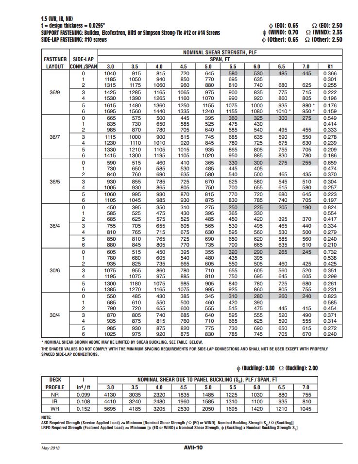
Typical diaphragm shear table from SDI’s DDM03. Image credit: SDI.

Since the tables in DDM03 are based solely on the fasteners and deck profiles included, determining diaphragm capacities utilizing any other proprietary fastener or deck profile fall on the designer or the proprietary product’s manufacturer. Enter Simpson Strong-Tie.

Our Steel Deck Diaphragm Calculator enables users to produce custom diaphragm tables similar to those in DDM03, generate detailed calculations using SDI equations based on project-specific inputs, as well as optimize deck fastening systems to ensure the most cost-effective design is utilized. The calculator incorporates our X-series steel decking screws, including the recently launched Strong-Drive® XL Large-Head Metal Screw, which has one of the highest capacities in the industry and in most cases, can be used as a 1-for-1 replacement of pins or 5/8 diameter puddle welds. (For additional information comparing Simpson Strong-Tie X-series and XL screws to pins or welds, review F-Q- STLDECK14.)
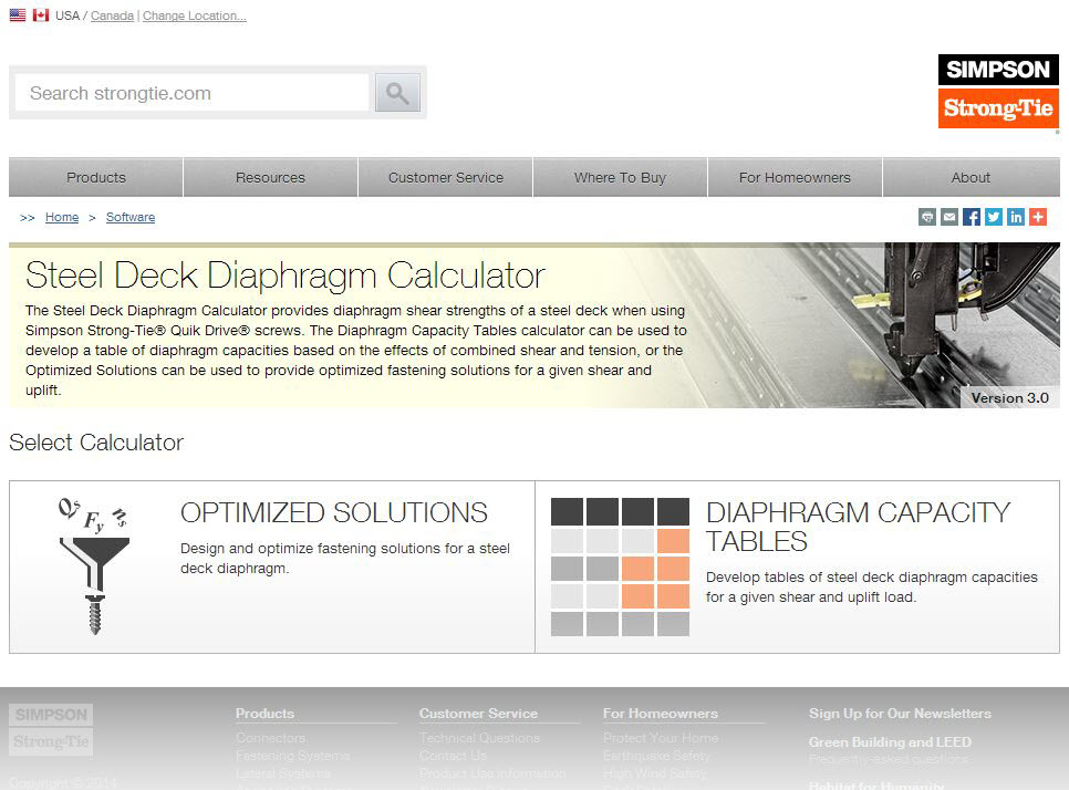
Decide whether to optimize a design or generate diaphragm tables.

The app can be used with minimal required input to generate tables and project-specific calculations. A more detailed analysis can be performed by inputting parameters for up to five unique zones, including overall dimensions, diaphragm shear, joist spacing, uplift and more.
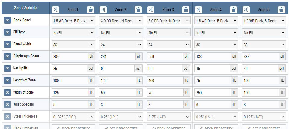
Input detailed information for up to 5 different zones on the same project.

One unfortunate aspect of many web apps is that your work is typically lost once you close your web browser. I’m happy to report that the folks here in our app development group have added the ability to save and upload project files. The calculator also provides a clean PDF printout of your results while giving you the option to generate a submittal package with supporting documentation, such as code reports, product approvals and installation recommendations.
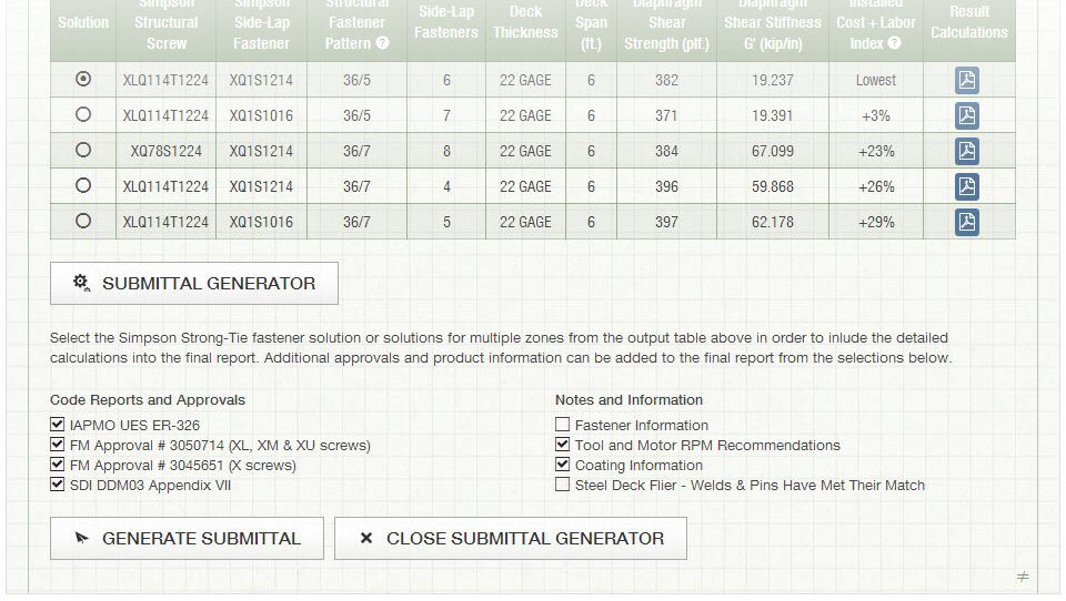
Generate a submittal that includes all calculations and necessary supporting documentation.

Try the revised Steel Deck Diaphragm Calculator yourself and let us know what you think. We always appreciate the feedback!

Steel Roof Decking

My wife, Kristin, sometimes gets angry with me while grocery shopping. It’s understandable. She’s asked me to grab some tomatoes or a loaf of bread and instead I’m just standing there looking up at the ceiling. Technically, it’s not a ceiling, but the underside of the roof, and I’m looking up to see the connection detailing, including whether or not the steel roof deck I’m looking at was welded, pinned, or screwed down to the steel joist, beam and angle supports.

If you’re a structural engineer, you might also do this inside your local supermarket, Target, Walmart or The Home Depot. Many of these “big box” stores are typically constructed of tilt-up concrete perimeter walls, tube steel interior columns, and roofs built of steel joists, girders and decking. Though Simpson Strong-Tie is well known in the light-frame wood construction industry, some may not know that we’ve long been developing and selling anchors and fasteners for commercial construction.

Outside of a few dips into a Verco or ASC steel decking catalog from my consulting days in Las Vegas, my first real foray into the steel decking industry was about two years ago. I was asked to assist in representing Simpson Strong-Tie as an associate member at the Steel Deck Institute’s (SDI) quarterly meeting held just down the road in Dallas in November 2011. Since joining SDI, my main focus has been to find out what the industry needs, both from the installer’s and designer’s standpoint for steel deck attachment. Though we’ve had a screw attachment offering for years, my colleagues and I have worked to develop a better overall system which now includes:

Continue Reading