


Hurricane season is in full swing, and we’ve had a record number of named storms to date. With each one, Mother Nature has taken the opportunity to remind us of her awesome power and teach us how we can improve our built environment in preparation for the next. One of the lessons we’re regularly reminded of is the importance of a successfully implemented continuous load path and its role in keeping a structure intact.
Author: Keith Cullum
Keith is a Branch Engineer at Simpson Strong-Tie. After graduating with a degree in Architectural Engineering from Cal Poly San Luis Obispo, he worked for an engineering consulting firm in Southern CA designing commercial structures in steel, concrete and masonry, and multi- and single-family residential structures in cold-formed steel and wood. Prior to joining Simpson Strong-Tie in 2012, he worked for a steel deck manufacturer performing R&D and providing product technical support and promotion. He is a LEED Accredited Professional (AP) and a registered Professional Engineer in multiple states (CA, TX, OK, KS, MO, AL, AR, and MS).
How to Select a Connector – Hurricane Tie
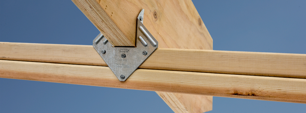
When it comes to wood-frame construction, hurricane ties are among the most commonly specified connectors. They play a critical role in a structure’s continuous load path and may be used in a variety of applications, like attaching roof framing members to the supporting wall top plate(s), or tying wall top or bottom plates to the studs. They are most commonly used to resist uplift forces, but depending on regional design and construction practices, hurricane ties may also resist lateral loads that act in- or out-of-plane in relation to the wall.
Simpson Strong-Tie manufactures approximately 20 different models of hurricane ties, not counting twist straps, other clips, or the new fully-threaded SDWC screws often used in the same applications. This assortment of models raises the question, “How do you select the right one?”
In this post, we’ll outline some of the key elements to consider when selecting a hurricane tie for your project.
Demand Load
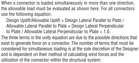
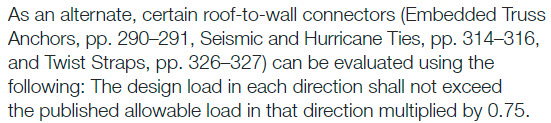
Let’s start with the obvious one. If your building’s roof trusses have an uplift of 600 lb. at each end, don’t select a hurricane tie with a published capacity of less than 600 lb. It’s also important to consider combined loading if you plan to use the tie to resist both uplift and lateral loads. When the connector is resisting lateral loads, its capacity to resist uplift is reduced. I won’t go into too much detail on this topic since it was covered in a recent blog post, but in lieu of the traditional unity equation shown in Figure 1, certain Simpson Strong-Tie connectors (hurricane ties included) are permitted to use the alternative approach outlined in Figure 2.
What if the tabulated loads in the catalog for a single connector just aren’t enough? Use multiple connectors! An important note on using multiple connectors, though: Using four hurricane ties doesn’t always mean you’ll get 4x the load. Check out the recently updated F-C-HWG23 High Wind Guide for allowable loads using multiple connectors and for guidance on the proper placement of connectors so as to avoid potential overlap or fastener interference.


Dimensional Requirements
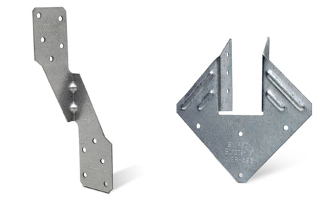
While the majority of the hurricane ties that Simpson Strong-Tie offers are one-sided (such as the H2.5A), some are designed so the truss or rafter fits inside a “U” shape design to allow for fastening from both sides (such as the H1). If using the latter, make sure the width of the truss or rafter is suitable for the width of the opening in the hurricane tie. For example, use our new H1.81Z (not the H1Z) for 1¾” wide engineered roof framing members.

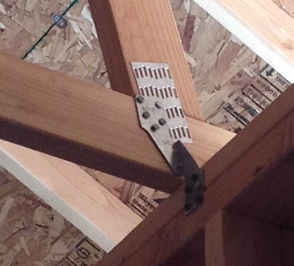
Additionally, the height of the hurricane tie and the wood members being attached should be compatible. For example, an H2.5A would not be compatible with a roof truss configured with only a nominal 2×4 bottom chord over the plate since the two upper nail holes in the H2.5A will miss the 2×4 bottom chord (see Figure 7). This is actually such a common mis-installation that we specifically tested this scenario and have a specific footnote in the table load about it (note the greatly reduced capacity). In this case the ideal choice would be the H2.5T, which has been specifically designed for a 2×4 truss bottom chord.

Fasteners with Hurricane Ties
It’s also essential to pay close attention to the diameter and length of the fasteners specified in the Simpson Strong-Tie literature. While many hurricane ties have been evaluated with 8d x 1½” nails for compatibility with nominal 2x roof framing, some require the use of a longer, 8d common (2½” long) nail and others require a larger-diameter 10d nail.
When specifying products for a continuous load path, it’s a good idea to select connectors that all use the same size nail to avoid improper installations on the job. It’s much easier if the installer doesn’t need to worry about which size nail he currently has loaded in his pneumatic nailer.
Wall Framing
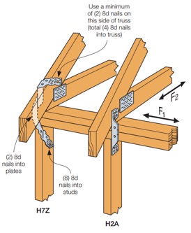
Do your roof and wall framing members line up? If so, creating a continuous load path can be made simpler by using a single hurricane tie to fasten the roof framing to studs. The H2A, H7Z, and H10S are some of the connectors designed to do just that. If your framing doesn’t align, though, you can use two connectors to complete the load path. For simplification and to reduce potential mix-ups in the field, consider selecting the same hurricane tie for your roof framing-to-top-plate and top plate-to-stud connections, like the H2.5A.
Besides the added benefit of fewer connectors to install, using a single hurricane tie from your roof framing to your wall studs can eliminate top-plate roll, a topic discussed at length in one of our technical bulletins.
Other Factors When Selecting Hurricane Ties
Some additional factors that may influence your selection of a hurricane tie are:
- Environmental factors and corrosion should be considered when selecting any product. Nearly every hurricane tie is available in ZMAX®, our heavier zinc galvanized coating, and several are available in Type 316 stainless steel. A full list of products available in ZMAX or stainless steel may be found on our website. On a related note, be sure to use a fastener with a finish similar to that of the hurricane tie in order to avoid galvanic corrosion caused by contact between dissimilar metals.
- When retrofitting an existing structure, local jurisdiction requirements will also influence your decision on which hurricane tie to use. As an example, the state of Florida has very specific requirements for roof retrofitting, which we outline in a technical bulletin, and they specifically mention the roof-to-wall connection. Be sure to check with your local city, county or state for specific requirements before you decide to retrofit.
- Availability of wind insurance discounts in your area could also affect your decision on which type of hurricane tie to use on your home. Your insurance company may provide a greater discount on your annual premium for ties that wrap over the top of your roof framing and are installed with a certain minimum quantity of nails. Check with your insurance provider for additional information and requirements.
Although this is a lot to take in, hopefully it makes choosing the right hurricane tie easier for you on your next project. Are there any other items you consider in your design that weren’t mentioned above? Let us know in the comments below.

Our Latest Online Resource: Steel Deck Diaphragm Calculator
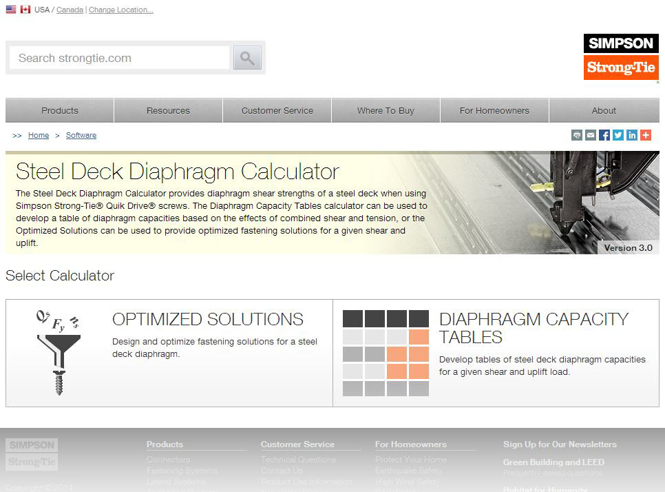
Although Simpson Strong-Tie is best known for our structural products: engineered structural connectors, lateral systems, fasteners and fastening systems, anchoring products and most recently, concrete repair, protection and strengthening (RPS) systems, we are continually developing new and exciting software solutions. As we’ve discussed in prior blog posts, Simpson Strong-Tie has numerous software programs and web and mobile apps available for download or online use at www.strongtie.com/software. Today, I’d like to review our recently launched web app, the Steel Deck Diaphragm Calculator. The calculator is accessible from any web browser and doesn’t require downloading or installing special software.
While the method of designing and specifying a steel deck and its attachment can vary by region, most designers are familiar with the Steel Deck Institute (SDI) and its Diaphragm Design Manual, 3rd Edition (DDM03). DDM03 presents diaphragm shear strength and stiffness equations for various steel deck profiles and commonly used attachment types (welds, power-actuated fasteners, or screws). The calculations can be quite tedious, so the SDI has developed numerous tables using these equations and placed them at the back of DDM03 for easy reference.
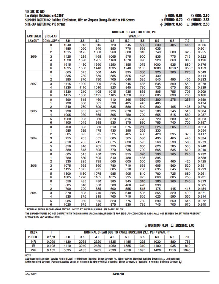
Since the tables in DDM03 are based solely on the fasteners and deck profiles included, determining diaphragm capacities utilizing any other proprietary fastener or deck profile fall on the designer or the proprietary product’s manufacturer. Enter Simpson Strong-Tie.
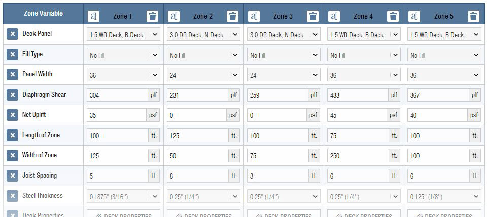
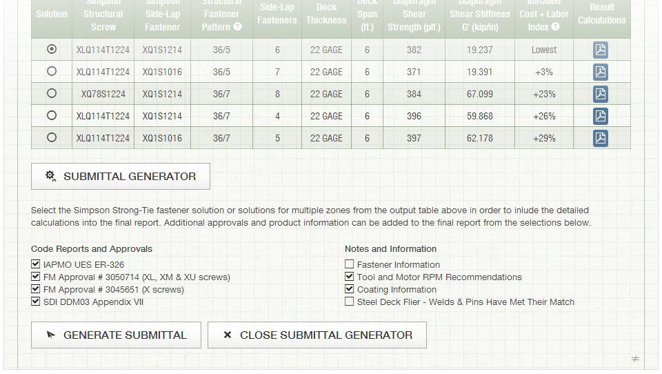
Our Steel Deck Diaphragm Calculator enables users to produce custom diaphragm tables similar to those in DDM03, generate detailed calculations using SDI equations based on project-specific inputs, as well as optimize deck fastening systems to ensure the most cost-effective design is utilized. The calculator incorporates our X-series steel decking screws, including the recently launched Strong-Drive® XL Large-Head Metal Screw, which has one of the highest capacities in the industry and in most cases, can be used as a 1-for-1 replacement of pins or 5/8 diameter puddle welds. (For additional information comparing Simpson Strong-Tie X-series and XL screws to pins or welds, review F-Q- STLDECK14.)
The app can be used with minimal required input to generate tables and project-specific calculations. A more detailed analysis can be performed by inputting parameters for up to five unique zones, including overall dimensions, diaphragm shear, joist spacing, uplift and more.
One unfortunate aspect of many web apps is that your work is typically lost once you close your web browser. I’m happy to report that the folks here in our app development group have added the ability to save and upload project files. The calculator also provides a clean PDF printout of your results while giving you the option to generate a submittal package with supporting documentation, such as code reports, product approvals and installation recommendations.
Try the revised Steel Deck Diaphragm Calculator yourself and let us know what you think. We always appreciate the feedback!

How Heavy Are Your Calculations?
Designing my first building was truly a learning experience. I remember one event in particular when I determined the required thickness for a steel column base plate. That day I wrote “1.5-inch thk. min.” on my calc pad and months later while out walking the job, I got to see that 1.5-inch thick plate in the flesh. Let me tell you, it was much thicker and heavier in-person than on my calc pad. This eye-opening experience – the realization that what you’re designing isn’t just a word or a number, but rather a physical object with width, height, length and weight – is something every structural engineer goes through early in their career. Designing something on paper doesn’t convey those physical properties very well.Continue Reading