Project Profile: Special Moment Frame Dropped-Beam Solution Saves Day(light) by Preserving Window Openings

Simpson Strong-Tie recently had the opportunity to work with MAK Construction to come up with a rather unique solution for a residential project in Phoenix, Arizona. Our Strong Frame® Moment Frame Selector software was used by the engineer on record, L.R. Nelson Consulting Engineers, LLC, to design this truly “special” special moment frame (SMF). The challenge for this particular moment frame design was figuring out how to work around a large garage door opening on the bottom floor without obstructing the window openings on the next floor, because the standard SMF design would cause the beam to cross right through the middle of the windows as they were situated. The solution required dropping the beam below the top of the columns, something seldom seen in moment frame designs. However, our engineering services, in collaboration with L.R. Nelson Consulting Engineers, were able to determine that dropping the beam to the needed level would be quite feasible in this case, and within 24 hours a new design was sent to the EOR and to the contractor for final approvals, which were granted.

Continue Reading

Soft-Story Retrofits Using the New Simpson Strong-Tie Retrofit Design Guide

Thousands of soft-story buildings up and down the West Coast require retrofits to prevent collapse in the event of a major earthquake. Whether the retrofits are mandated by a city ordinance (as in San Francisco, Berkeley and Los Angeles) or are undertaken as voluntary upgrades, the benefits of adding necessary bracing to strengthen the ground story are immense. Simpson Strong-Tie has taken the lead, with our new Soft-Story Retrofit Guide, to provide information that helps engineers find solutions to reinforce soft-story buildings against collapse. We are also providing information on the two methods that can be used for the analysis and design of these soft story retrofits.

soft-story-retrofit-guideAfter the initial information section of the guide, a two-page illustrated spread (pp. 14–15) shows various retrofit products that could be used to retrofit the soft-story structure with reference to the following pages. Three main lateral-force-resisting systems highlighted in this graphic are the Strong Frame® special moment frame (SMF), the new Strong-Wall® wood shearwall, and conventional plywood shearwalls. Individual retrofit components are also shown, such as connection plates and straps for lateral-load transfer, anchors for attachment to the foundation, fasteners and additional products such as the RPBZ retrofit post base and AC post caps for providing a positive connection.

soft-story-product-illustrationTurning the page, you come to the section describing in detail the many benefits of the Strong-Frame special moment frame (SMF) in a retrofit situation. The engineered performance of the SMF provides the additional strength and ductility that the building requires and can be fine-tuned by selecting various combinations of beams, columns, and Yield-Link® structural fuse sizes. A typical retrofit Strong Frame® SMF comes in three complete pieces allowing for the frame to be installed on the interior of the structure in tight quarters. The frame is simply installed using a 100% snug-tight field-bolted installation with no on-site welding or lateral-beam bracing required.

field-installation-beam-to-columnThe next lateral system we focus on is the Strong-Wall® shearwall and the new grade beam solutions offered to reduce the concrete footprint. The new Strong-Wall wood shearwall includes an improved front-access holdown and top-of-wall connection plates for easier installation. Both the Strong Frame SMF and the Strong-Wall wood shearwall have load-drift curves available for use with FEMA P-807. Site-built shearwalls can be installed using retrofit anchor bolts at the mudsill and new holdowns at the shearwall end posts.

strong-wall-wood-shearwall-pushover-curveIn the pages following the lateral systems, various products are shown with tabulated LRFD capacities, whereas ASD capacities are typically provided in the order literature for these products. Both ASD and LRFD capacities have been provided for products with new testing values such as the A35 and L90 angles installed with ⅝”-long SPAX screws into three different common floor sheathing materials, as well as for the new HSLQ heavy-shear transfer angle designed to transfer higher lateral forces directly from 4x blocking to the 4x nailer on the Strong-Frame SMF, even when a shim is used between the floor system and the frame. LRFD capacities are provided in this new Soft-Story Retrofit Guide specifically for use with the FEMA P-807 design methodology. This methodology specifies in section 6.5.1 that:

Load path elements should be designed to develop the full strength and the intended mechanism of the principal wall or frame elements. Therefore, to ensure reliability, appropriate strength reduction factors should be applied to the ultimate strengths of load path elements. Specific criteria may be derived from principles of capacity design or from other codes or standards, such as ASCE/SEI 41 or building code provisions involving the overstrength factor, Ωo.

FEMA P-807 bases the capacity of the retrofit elements on the peak strength. LRFD capacities are provided for various load-path connector products, which can be used to develop the full strength of the lateral-force-resisting element to satisfy this requirement.

typical-a35-hslq412-installationWrapping up, the guide focuses on the various free design tools and resources available for the evaluation, design and detailing of the soft-story structure retrofit. These tools include the Weak Story Tool with Simpson Strong-Tie® Strong Frame® Moment Frames, Design Tutorials for the WST for both San Francisco– and Los Angeles–style buildings, our Soft-Story Retrofit Training Course offering CEUs, Strong Frame Moment Frame Selector Software, Anchor Designer™ Software for ACI 318, ETAG and CSA, and tailored frame solutions using our free engineering services.

soft-story-documentsFor other information regarding soft-story retrofits, refer to previous blogs in “Soft-Story Retrofits,”  “City of San Francisco Implements Soft-Story Retrofit Ordinance,” and “Applying new FEMA P-807 Weak Story Tool to Soft-Story Retrofit.”


Special Moment Frame Installation: What Structural Engineers Should Watch For

Launched in January 2013, the Simpson Strong-Tie® Strong Frame® special moment frame (SMF) has been successfully used on many projects around the country. We’ve explored several aspects of the frame in previous blog posts, including beam bracing requirements, soft story retrofits, and the San Francisco retrofit ordinance. If you have specified the Strong Frame SMF on your project, here are a few helpful items to review during your structural observations at installation.

When the special moment frame is ordered, Simpson Strong-Tie sends the contractor a frame verification sheet to verify the dimensions (Figure 1). It is not uncommon for minor adjustments to be made to accommodate specific field conditions. We recommend the framer follow up with the Designer to ensure the needed modifications do not alter the design of the frame based on deflection or strength stand point limitation(s). Once we receive the signed verification, we begin fabricating the frame. The accompanying concrete anchors are usually shipped before the frame so they can be placed ahead of time.
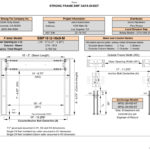
SMF Data Sheet v2.2.2.xlsmIt all starts with the concrete! The majority of misinstallation issues involve anchorage placement. Anchors not placed correctly can alter the frame that’s already been ordered, affecting lead times or requiring retrofit to properly transfer the frame forces into the concrete. Contact your local Simpson Strong-Tie sales rep to help with any questions.

Placement of the Moment Frame Shear Lug (MFSL) is critical to ensure proper transfer of shear forces into the foundation. If you are visiting the jobsite prior to concrete placement, take a look at the orientation of the MFSL. The MFSL contains back-to-back structural angles placed at the top of concrete to transfer the shear component of the Strong Frame SMF forces into the concrete. Figure 2 shows the proper placement of the MFSL and template in relationship to the direction of the column.
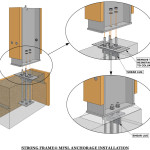
Proper Installation of MFSL in relationship to the Column
Figure 2: Proper Installation of MFSL in relationship to the Column

The template has a similar appearance to the shape and size of the column base plate, which sometimes leads to the tendency to orient the template 90 degrees from its proper installation, as shown in Figure 3. The template has two half circles at the center of the anchor bolts for proper measurement (center-to-center of columns) by the contractor, as shown in Figure 4.
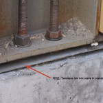
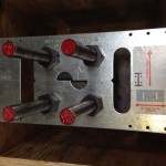
Figure 3:  Improper orientation of MFSL Template
Figure 3: Improper orientation of MFSL Template
Top View of MFSL Template
Figure 4: Top View of MFSL Template

The templates are temporary and intended to be removed prior to frame installation (unlike the case in Figure 3). So placement of the shear lugs is more critical to verify than the direction of the template, since the contractor may remove the template and reinstall it in an alternate orientation. The vertical legs of the two structural angles should intersect the column’s weak axis (perpendicular to center of frame) as shown in Figure 5, and should not be placed parallel to the strong axis.
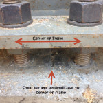
Proper Orientation of MFSL
Figure 5: Proper Orientation of MFSL

According to ASTM A325, installation requires 11 bolts snug tight at each beam-column connection (labeled “a” in Figure 6), and the column needs to be attached to the four anchor bolts into the base of each column. Many components of the Strong Frame SMF are factory-installed, including the Yield-LinkTM structural fuses, Buckling Restraint Plates (BRP), and nailers. The Yield-Link fuses and BRP should not be disassembled. Figure 6 illustrates an instance where the BRP was loosened during erection. The BRP prevents the Yield-Link fuses from buckling when the frame is subjected to compression forces. Contact Simpson Strong-Tie if you encounter this in the field.
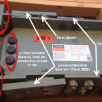
Figure 6:  Beam-Column Connection
Figure 6: Beam-Column Connection

The wood nailers may be replaced in kind. It is important to note that attachment of the nailers may not utilize all available bolt holes on the column and beam. Various holes are left unused for flexibility with installation of utilities and electrical wiring.

Lastly, often overlooked at installation are the required SDS screws through the column cap plate into the framing above (Figure 7). The SDS screws are included with the installation kit. They are required for bracing of the column on both faces of the column.
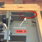
Figure 7:  Missing SDS screws for Column Bracing
Figure 7: Missing SDS screws for Column Bracing

How is the Strong Frame special moment frame working for you?  Please let us know in the comments!