


Design criteria for cracked-concrete masonry units are finally available for adhesive anchors.
It has been over 15 years since cracked concrete changed the way anchorage to concrete was qualified and designed. The ICC International Building Code (IBC) 2003 referenced American Concrete Institute (ACI) 318-02 Appendix D as a design provision for both cast-in-place and post-installed anchors into concrete. Appendix D was the first introduction of cracked concrete to designers. These design provisions required mechanical anchors to be qualified per ACI 355.2, which mandated testing of anchors in cracks. The Masonry Society (TMS) 405 has not addressed cracks in concrete masonry units since the code’s introduction to concrete in 2003. The Concrete and Masonry Anchor Manufacturers Association (CAMA) has taken on the task of introducing cracked masonry unit testing, qualification and design by updating Acceptance Criteria AC58. These criteria were developed to address the testing and qualification of adhesive anchors in grouted, hollow, and partially grouted concrete masonry units, as well as in brick masonry units.
We’ve composed this blog post to help keep you informed of the new design provisions being proposed in ICC-ES. At the end of this article, you’ll have the opportunity to provide comments directly to ICC-ES. It’s advisable to download the proposed criteria at the following link to follow along as you read this post.
https://icc-es.org/wp-content/uploads/2019/08/1-AC58-1019-R1.pdf
History
AC58 was first issued by ICC-ES in 1995 to address the performance parameters of adhesive anchors in both concrete and masonry. It included adverse service condition tests for these anchors such as dampness, elevated temperature and sustained load. However, the criteria were limited to uncracked concrete and masonry. In 2006, AC308 was introduced to address adhesive anchors in both cracked and uncracked concrete and to require the use of strength design as opposed to allowable stress design. The new criteria included testing in adverse conditions, derived from AC58. The issuance of AC308 required AC58 to be modified in late 2006 to cover only uncracked masonry base materials for adhesive anchors using allowable stress design. As the acceptance and use of AC308 has grown, it became clear AC58 needed to be updated to cover both cracked and uncracked masonry.
Tests
The test regimen in the revised AC58 mirrors the test regimen of AC308, and is broken into three categories:
- Reference tests: Tests conducted in grout-filled masonry in the center of the cell, bed joint, web and top of wall. In addition, testing may be conducted in a cracked bed joint.
- These tests are used to establish the nominal bond strength for the adhesive anchor in uncracked masonry and cracked masonry.
- Reliability tests: Tests conducted in grout-filled masonry in partially cleaned holes, water-saturated masonry, freezing and thawing conditions, sustained loads, installation direction and large crack widths.
- These tests determine the anchor category for the product and generate reduction factors that are applied to the nominal bond strength of the anchor.
- Service-condition tests: Tests conducted in grout-filled masonry at elevated temperatures, at decreased installation temperatures, and for resistance to alkalinity and sulfur. In addition, seismic tension and shear testing may be conducted.
- These tests establish temperature range and environmental exposure limits for the product. The seismic tests generate reduction factors that are applied to the nominal bond strength of the anchor.
AC58 also includes test programs for hollow masonry and brick wall construction. The tests required in these base materials are similar to the tests noted above.
Design changes
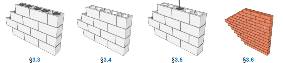
Section 3.0 of the revised AC58 introduces design provisions that should be used for products qualified by these criteria. These designs were derived from ACI 318-14 Chapter 17, Anchorage to Concrete (Appendix D prior to 2014). The uniform bond model for adhesive anchors contained in ACI 318 has been shown to represent the behavior of adhesive anchors in grouted masonry. CAMA proposes modifications to the existing ACI 318 design provisions to accommodate the uniqueness of grouted concrete masonry units. Table 3.1 in AC58 summarizes the sections within ACI 318 that were modified to accommodate grouted concrete masonry units. These provisions are to be applied to structures assigned to Seismic Design Category (SDC) C, D, E and F. Due to the expected brittle failure of the masonry units, the maximum tension and shear design load combinations that should be applied to these provisions are combinations that include E, with Eh increased by Ωo. Provisions for strength design in concrete masonry units are broken out in several sections. Section 3.3 of AC58 provide the strength design provisions for fully grouted masonry units. The subsections of 3.3 provide the details of calculating the concrete and bond capacities, with modifications to accommodate the unique property of grouted masonry units.
As in concrete applications, the method for determining the design strength of adhesive anchors in grouted masonry compares three different failure modes, as defined in section 3.3.2.4.3 of AC58.
- φNsa, steel failure of anchor rod for a single anchor.
- 0.75φNmb, masonry breakout.
- 0.75φNma, bond strength of adhesive in masonry.
These calculated design strengths shall be compared to the calculated factored loads as shown in Table 3.2 of AC58. The strength reduction factors, φ, multiplied by the nominal strength, have been modified to accommodate the failure modes associated with concrete masonry units; these are defined in section 3.3.2.9 of AC58.
The nominal breakout strength is defined in section 3.3.2.11. The definition has been modified from ACI 318-14. As with concrete, the nominal breakout strength is calculated using modification factors multiplied to a basic masonry breakout strength. The basic masonry breakout strength has been defined in section 3.3.2.12. The change made in this equation is the calculation of the effectiveness factor, km, for breakout strength in masonry. km for masonry materials is defined as a reduction factor of 0.7 multiplied by the effectiveness factor for breakout strength in concrete, kc. The reduction factor of 0.7 was proposed by CAMA in AC58 due to the lack of testing of post-installed adhesive anchors in concrete masonry units.
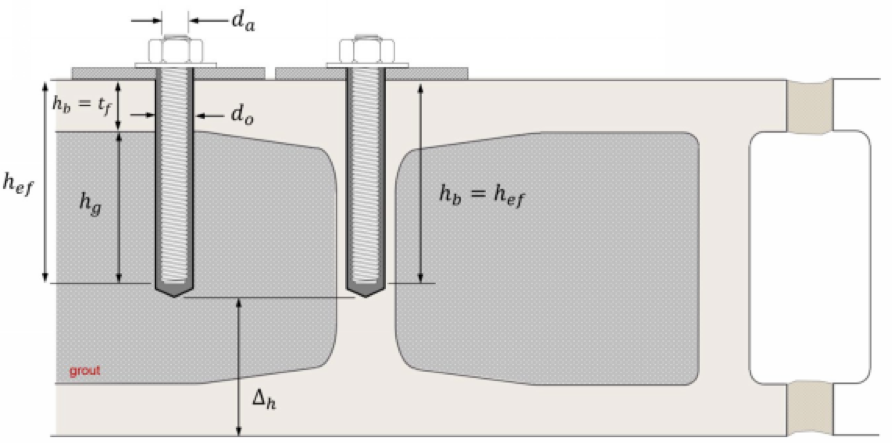
As in concrete applications, the nominal adhesive bond strength in masonry shall be calculated per section 3.3.2.10. The basic bond strength that is utilized in the nominal bond strength is calculated per section 3.3.2.11. In the basic bond strength, the effective embedment, kef, had to be defined. Figure 2 below provides guidance on dimensional parameters as defined in section 1.5 of AC58.
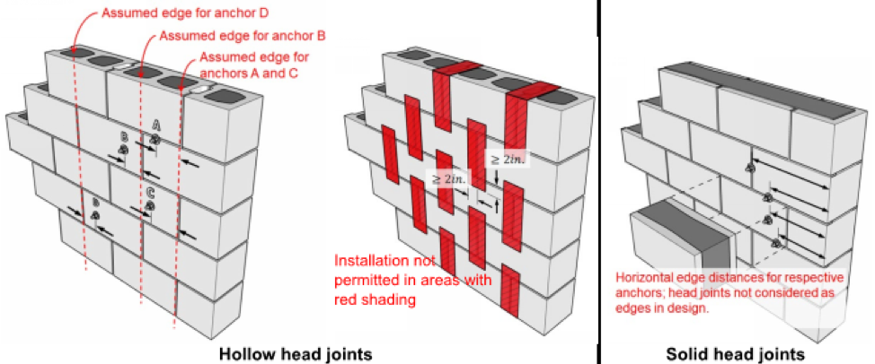
Voids in grouted masonry units are common. AC58 provides definition of the edge distances associated with grouted masonry. Figure 3 shows how the criteria definethe edge distances associated with the adhesive anchors qualified per this criterion.
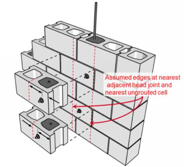
Design provisions were also provided for ungrouted concrete masonry units. Section 3.4 of the criteria provides the details associated with calculating the strength in ungrouted concrete masonry units. Figure 4 below shows the dimensional parameters for ungrouted masonry units.
Unlike in grouted masonry units, the critical edge and spacing requirements are defined in AC58 in table 3.3 below.
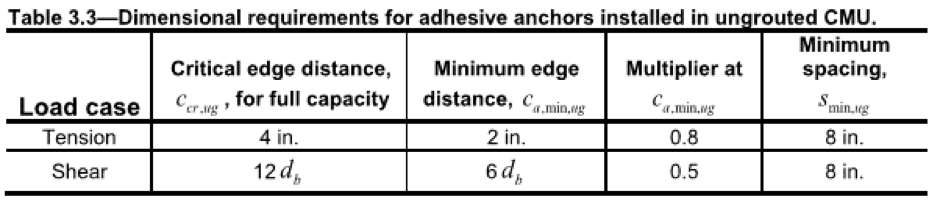
You may wonder what happens if your anchors are spaced less than the prescribed dimension in table 3.3. Unlike for grouted masonry, group anchor calculations for ungrouted masonry arenot permitted. Section 3.4.2.3.2 of AC58 states that the design strength of any group of anchors spaced less than 8″ apart shall be calculated as the strength of a single anchor.
Provisions required to calculate the strength of partially grouted masonry can be found in section 3.5 of AC58. Mixture of grouted and ungrouted provisions shall be used for design of anchors in partially grouted concrete masonry units. Section 3.5.3 defines what to do if your anchor falls within the grouted part of the cell or parts of the cell that are not grouted.
Edge distances are unique in partially grouted masonry units. Figure 5 below shows the edge distances to consider if the location of the grouted cells are known. If the locations of grouted cells are unknown, the design of anchors shall be in accordance with the Ungrouted provisions in section 3.4 of AC58.
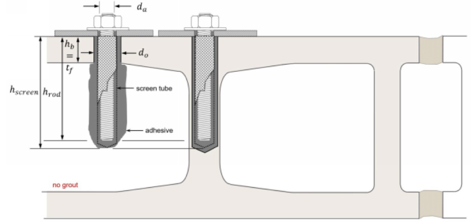
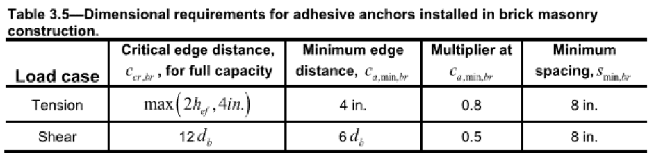
Clay brick masonry construction also has design provisions in section 3.6 of AC58. Figure 6 below provides the dimensional parameters of brick unit masonry.
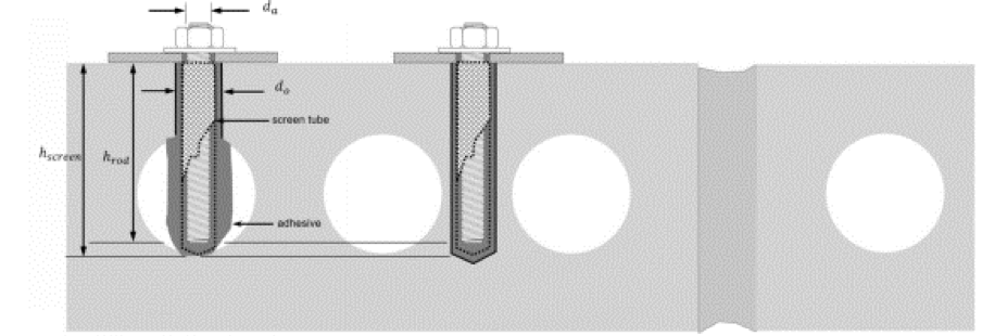
The provisions for this type of masonry units are similar to ungrouted masonry units. The edge and spacing requirements are prescribed in table 3.5 in AC58, see below. A screen tube must be used when installing into this type of substrate. Any spacing of a group of anchors less than 8″ apart shall be considered as a single anchor.
These proposed design changes for grouted, hollow, and partially grouted concrete masonry units, and for brick masonry units are very different from the current TMS 405 being enforced in the masonry design community. Designers are now faced with two different design methodologiesif they’re designing a cast-in-place rather than a post-installed masonry anchor. The new evaluation reports that will be qualified per AC58 will have design examples to give professionals the necessary guidance in selecting the best adhesive solution.
Status of the revised AC58
The revised AC58 will be reviewed and considered for adoption at the ICC-ES Evaluation Committee hearing in early October 2019. The document is currently posted on the ICC-ES website for review, and comments from interested parties will be accepted by ICC-ES until September 10, 2019. You’re encouraged to read the document and submit any comments you may have directly to ICC-ES.
What’s next?
Once the revised AC58 is adopted by ICC-ES, similar revisions will need to be made to AC01 (Acceptance Criteria for Expansion Anchors in Masonry Elements) and AC106 (Acceptance Criteria for Predrilled Fasteners — Screw Anchors — in Masonry). I can report that work in this direction is currently underway, using a test regimen that mirrors the test regimen of AC193 (Acceptance Criteria for Mechanical Anchors in Concrete Elements). In addition, since AC193 addresses both expansion anchors and screw anchors, it is most likely that a revised AC01 will also include screw anchors.
How can you participate?
Do you agree with the new design methodology proposed in the new AC58?
Do the design strength differences between cast-in-place anchors designed per TMS 405 and post-installed adhesive anchors qualified and designed per AC58 make sense to you?
Do the cracked widths proposed in these criteria make sense for grouted masonry units?
Do you believe this new design methodology and its proposed qualification need more research?
If you have these or other questions after reading this blog post, you’re encouraged to review the revised AC58 in its entirety. This document is available for public review on the ICC-ES website. Click on the link below to download the proposed criteria. Should you have comments about anything contained in the document, you can submit those comments directly to ICC-ES by email at es@icc-es.org. Public comments are welcome through September 10, 2019.
Download the proposed criteria here.
..
Don’t let the Cracked Grouted Masonry design provisions sneak up on you the way Cracked Concrete may have in 2003. Be part of the review process and provide your comments to ICC-ES before the revised AC58 goes into enforcement.
Authors: Chris LaVine, Marlou B. Rodriguez, S.E.
