

We’re entering the year 2024 — welcome to the world of cracked and uncracked masonry. The last time Simpson Strong-Tie wrote a blog post regarding design criteria for post-installed anchors in masonry was in 2019, and ICC-ES was considering the adoption of a revised version of AC58, the Acceptance Criteria for Adhesive Anchors in Cracked and Uncracked Masonry Elements. Acceptance Criteria, or ACs, outline the testing that a manufacturer must comply with in order to get an evaluation report. In some cases, the ACs contain calculations methods if they are otherwise unavailable. If you missed the previous blog post, here is a link so you can explore a bit of the history that has led us to where we are today.
Since 2019, much has changed in the post-installed anchor world — the revised AC58 was adopted, approved, and compliance with the new acceptance criteria is now required to obtain a valid evaluation report through ICC-ES. Additionally, a revised Acceptance Criteria for Mechanical Anchors in Cracked and Uncracked Masonry Elements (AC01) has been published. However, a compliance date for the revised criteria has not yet been determined.
The purpose of this blog post is to highlight some of the major changes within the revised AC58 criteria, explain the impacts of the new standard on adhesive anchor design in masonry, and present a technical resource that contains design tables and detailed calculation examples in accordance with the new criteria.
First, what is “cracked” masonry?
In practice, brittle substrates, such as concrete and masonry, are known to crack. The presence of cracking in proximity to an anchor affects the anchor’s performance, and the revised AC58 aims to capture that behavior.
There are two main considerations when determining whether you need to consider cracked or uncracked masonry. The first consideration is the assigned Seismic Design Category (SDC) of the element considered. AC58 section 3.3.2.4 addresses the design of anchors in structures assigned to Seismic Design Category C, D, E, or F and states in a following subsection that cracked masonry should be assumed unless it can be demonstrated otherwise. This is mirrored in ACI 318-19 Section 17.10 for cracked concrete.
The second item to consider is a comparison of the service-level stress to the modulus of rupture for the type of mortar and wall construction, as stated in Section 5.12 of ICC-ES ESR-4844 (copied from AC58). If the maximum tensile stress calculated under service load demand exceeds the rupture modulus, then cracking must be assumed. An example of this would be checking a masonry wall experiencing out-of-plane flexure to determine whether the stress on the tension face exceeds the rupture modulus.
Revised Testing Protocol — Similarities and Differences
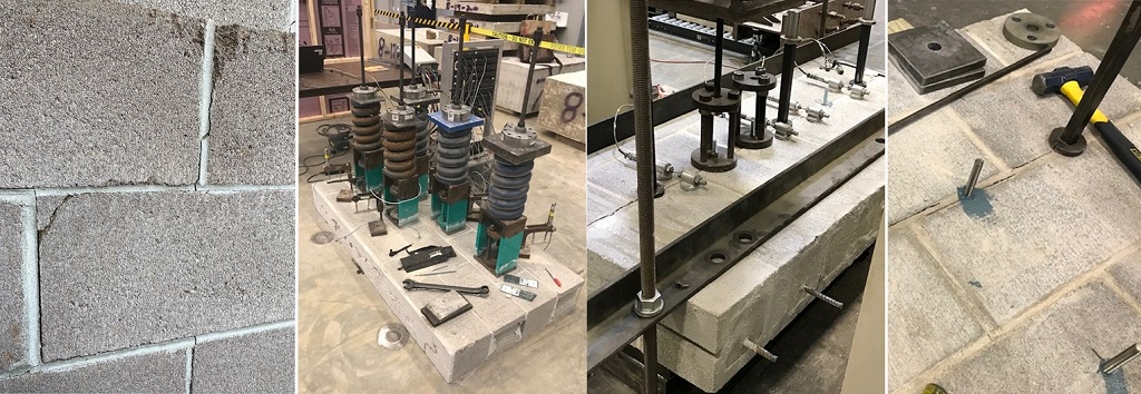
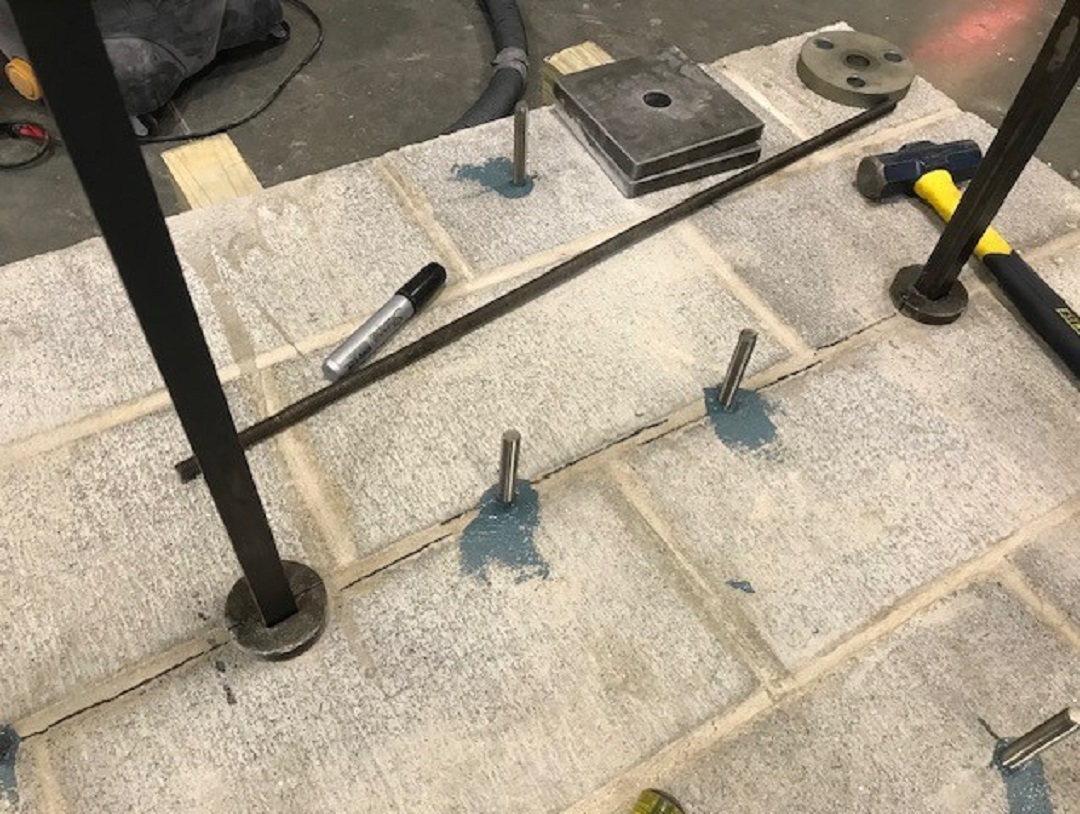
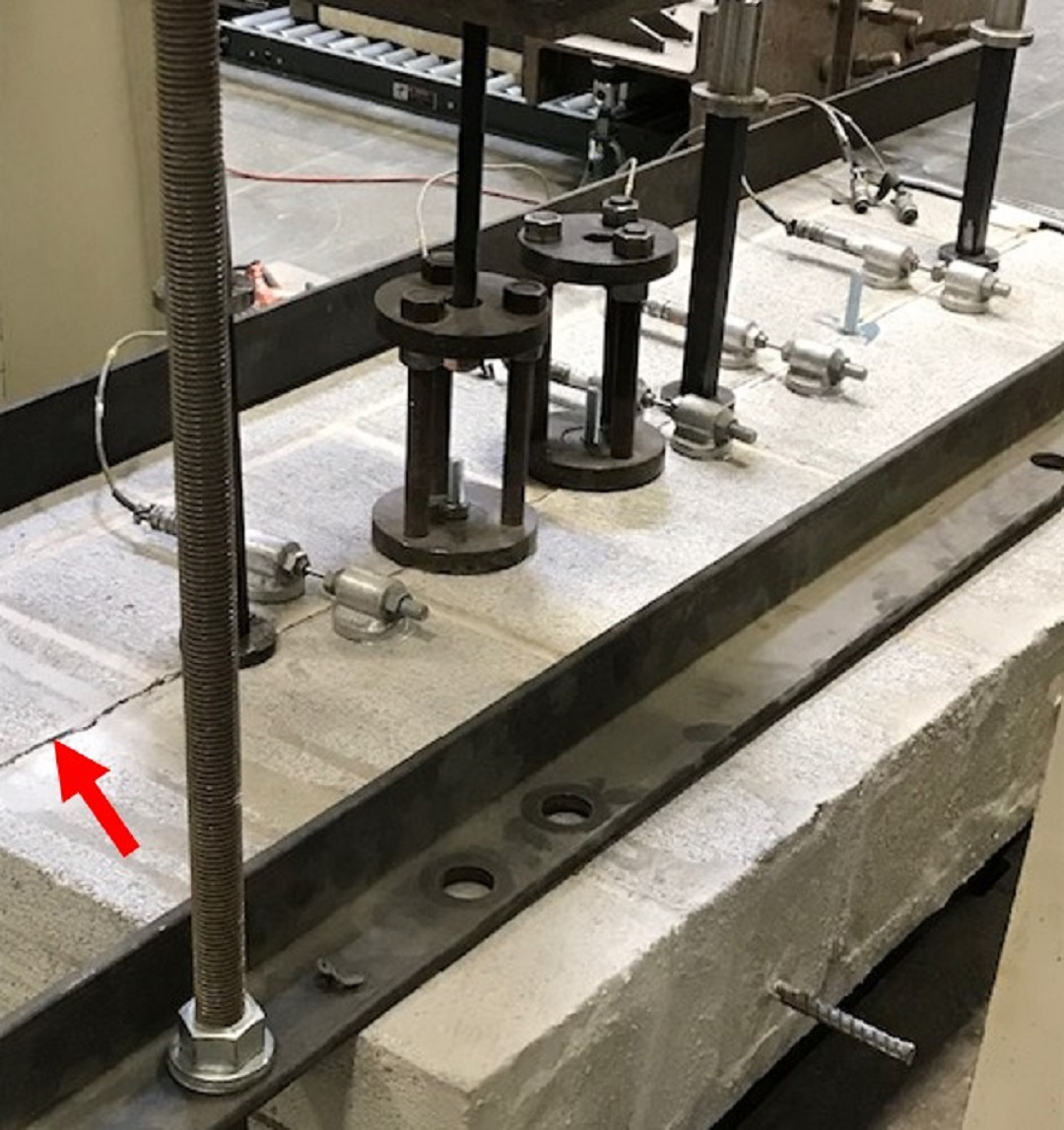
As stated in the previous blog post, the revised AC58 mirrors the test protocol of AC308, the Acceptance Criteria for Post-Installed Adhesive Anchors in Concrete Elements. As with its predecessor, the revised AC58 criteria allows for testing into fully grouted, partially grouted, and hollow concrete masonry units (CMU) in addition to clay brick masonry. However, in the revised criteria, anchors must be tested into cracks 0.012 inches wide for select reference tests and 0.020 inches wide for select reliability and service-condition tests to gain cracked-masonry approval. Reference tests must be completed per AC58 to achieve uncracked-masonry approvals as well. An explanation of the reference, reliability, and service-conditions tests can be found in the previous 2019 SE Blog post that I referenced earlier, as these AC58 test categories were new at the time. The image below was captured during one of the confined cyclic tension tests, where a crack is visible in the bed joint of the test subject, as indicated by the red arrow. For those doing work in high-seismic regions, you’ll also be happy to hear that the revised AC58 also includes a test protocol for hollow (ungrouted) CMU subjected to seismic loading.
Design of Anchors into Masonry
While the updates to the testing protocol are an interesting topic, even more relevant to our discussion are the changes to the design standards for adhesive anchors in masonry. The information contained within the previous AC58 was primarily related to test protocol and the post-processing of data to determine an allowable load that manufacturers could publish for their adhesive anchor products. In contrast, the revised AC58 now contains information that is extremely relevant to designers. Which raises several questions.
As a designer, why do I care what is included in the Acceptance Criteria?
The revision to AC58 provides the design equations necessary to determine the strength-level capacities of post-installed adhesive anchors for an array of failure modes. Because The Masonry Society (TMS) 402 does not currently provide calculation guidance for post-installed adhesive anchors, these calculation methods and equations are included in the revised AC58. And don’t worry if your firm does not have access to the revised version of AC58 —evaluation reports for adhesive anchors that are compliant with the new criteria all contain these equations in the body of the report.
What are the new design equations for adhesive anchors in cracked masonry?
Until recently, the capacity of an adhesive anchor was presented as an allowable load based on testing. This value was representative of the failure of the test specimen and encompassed potential failure within either the masonry or the adhesive. Now designers must check multiple failure modes to determine the controlling strength-level capacity of the connection. If you’re familiar with ACI 318 Chapter 17 for anchoring to concrete, then you’re already familiar with many of these failure modes and their associated calculations. ICC-ES has provided alterations to the ACI 318 equations in order to adapt them to masonry substrates; however, the bulk of the equations have remained very similar. AC58 directly references ACI 318 in multiple instances, deferring to the concrete code for the basis of calculation. That being said, there are multiple tweaks to modification factors, phi factors, and notations, so it’s not quite as simple as replacing f’c with f’m and moving on.
Below you will find a list of the failure modes to be checked for an adhesive anchor in grouted CMU. Table 1B is taken from the evaluation report for SET-3G, ICC-ES ESR-4844. Remember, prior to this revision to the Acceptance Criteria, there were no calculations for various limit states, so this is a major change in the design of adhesive anchors moving forward.
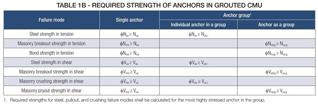
Of the seven failure modes shown in the table, six are recognized by ACI 318 Chapter 17 for post-installed adhesive anchors. The one unique failure mode that has been added to the list is “Masonry Crushing Strength in Shear.” This failure mode aims to capture the local crushing failure of the anchor against the masonry block. Equation 4-1 from Section 4.2.19 of ICC-ES ESR-4844 (shown below) provides the empirical equation that is a function of masonry strength and the shear area of the steel insert.
![]()
It’s also worth noting that many of these failure modes contain parameters that can only be determined through testing. Therefore, evaluation reports for specific adhesive anchors should be referenced during design.
Practical Considerations
Although calculations for strength-level design of adhesives in masonry mimic those for concrete, there are stark differences in construction using the two different materials. For practical reasons, the use of supplemental reinforcement to restrain breakout is not recognized in the revised AC58. Additionally, the revised AC58 states anchor edge distance, when measured along the horizontal plane, must consider the presence of joints when working with block consisting of hollow head joints. This topic is addressed in the previous blog post and can also be found in Section 4.1.3 of ICC-ES
How would I design anchor edge distance to hollow head joints in a ledger application?
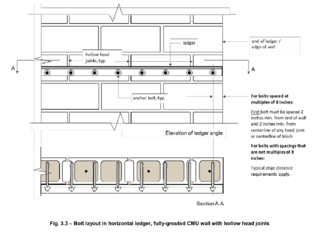
In practice, control of anchor locations relative to hollow head joints when anchoring wood or steel ledgers to the face of CMU may be difficult due to physical constraints or contractor practices. For this reason, AC58 now includes an optional calculation for ledgers anchored to grout-filled CMU that can be used when strict control of anchor location is not needed. Copied from AC58 into ICC-ES ESR-4844, Section 4.2.20 provides an enveloped calculation method for ledger shear capacity where breakout and pryout are evaluated at an “average” edge distance of 4″ from hollow head joints. To comply with the provision, the location of the first bolt and the spacing of bolts thereafter must meet the requirements as defined in Figure 3.3 of AC58 below.
Current State of Adoption
At this time, AC58 has not been formally recognized or adopted by The Masonry Society (TMS) 402. Therefore, it’s up to the Authority Having Jurisdiction (AHJ) to decide whether strength design methods are required. However, a current evaluation report is often required when utilizing adhesive anchors into masonry.
Resources
Long story short, changes are underway in the world of masonry, and Simpson Strong-Tie wishes to comply with the most current testing and design methods available.
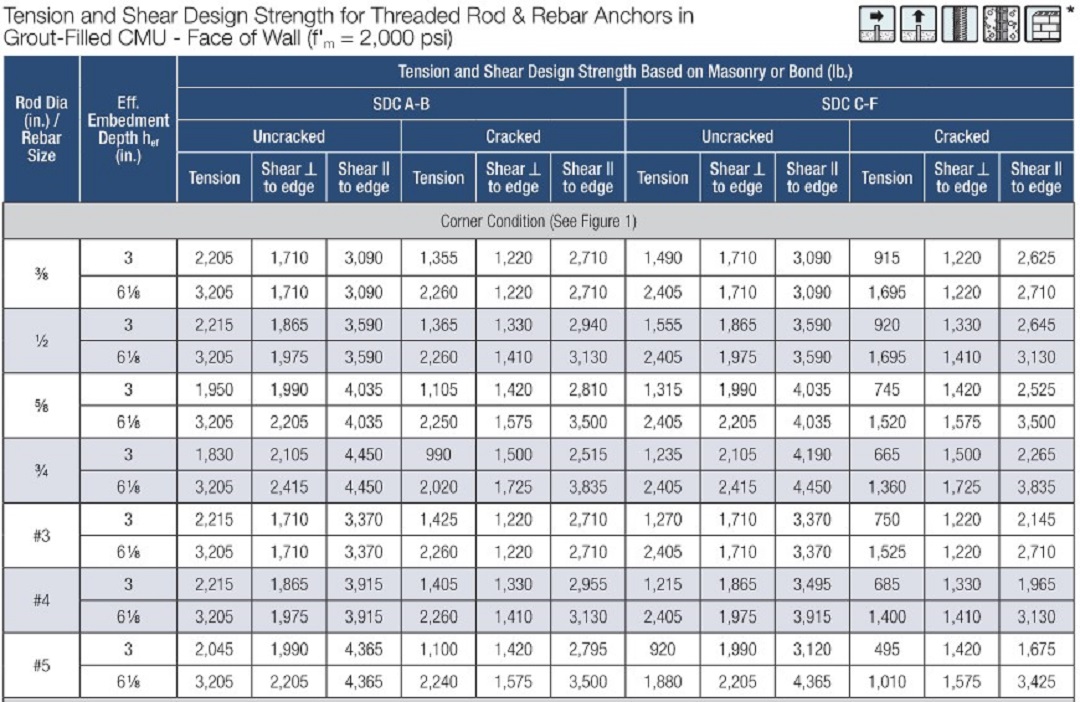
To assist engineers with the design of adhesive anchors into cracked and uncracked masonry, Simpson has released the Technical Engineering Bulletin (TEB), TEB-A-SET3GCMU24. The contents of this bulletin include a series of design tables with precalculated values based on anchor properties, loading, and masonry characteristics in addition to two in-depth design examples. An example table for strength-level capacities in grout-filled CMU is shown in Figure 4 below. Several other tables in the TEB capture hollow CMU, allowable capacities, top-of-wall installation, and varying edge distance.
Additionally, Simpson will soon debut the Anchor Designer™ for Masonry software, which will perform calculations to the new AC58 standard and house all current testing information relative to both mechanical and adhesive anchors. This software will have much of the same functionality as the Anchor Designer for concrete, and it will allow designers to design for anchors in masonry in accordance with the new methodology.

Be on the lookout for the Anchor Designer for Masonry software release and for future information regarding changes in testing and design for mechanical anchors into cracked and uncracked masonry.
