

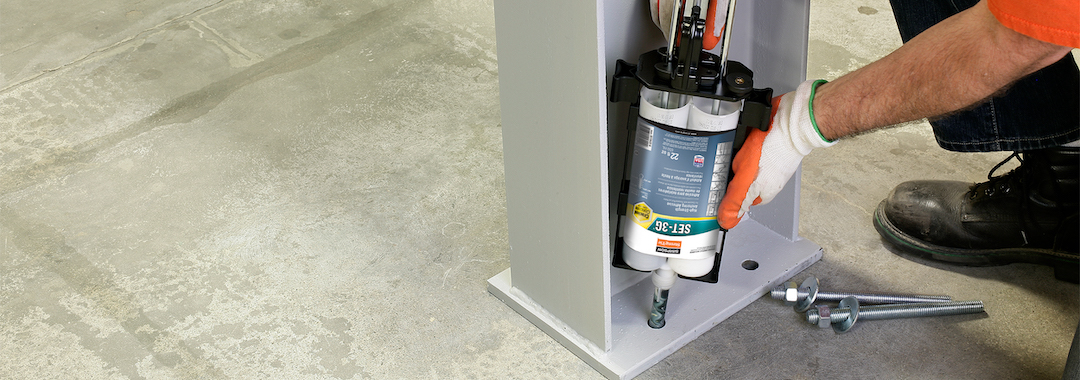
Have you ever been involved on a project where a post-installed anchor failed when loaded? What was the circumstance? Was the anchor installed with incorrect torque or was the hole improperly cleaned, resulting in lower capacities than published? Unfortunately, in the world of concrete anchors, installations are sometimes incorrect as a result of not following instructions. Alternatively, perhaps you’re working on a project where special inspection wasn’t performed as required by the building code. What should be done in these cases?
Visually, there isn’t always a good way to determine whether an anchor was installed correctly. Therefore, proof loading is often recommended or required. Engineers located in California know that certain hospital and school projects require proof loading as part of the California Building Code (CBC) “A” chapters or other specific CBC chapters. For those unfamiliar, the Division of the State Architect (DSA) regulates California K-12 school structure construction, and the Office of Statewide Health Planning and Development (OSHPD) regulates California healthcare structure construction. Each agency has different requirements for performance levels dictated by the importance and occupancy of the structure.
This blog is not going to cover all of the special inspection requirements for post-installed anchors, but there are a few important things to note. First, Table 1705.3 of both the International Building Code® (IBC®) and the CBC require a minimum of periodic special inspection for all mechanical and adhesive anchors post-installed into hardened concrete members. Second, both ICC-ES ESR and IAPMO-UES ER evaluation reports contain specific requirements for special inspection. Third, see the link below for additional information regarding “GUIDELINES FOR SPECIAL INSPECTION AND STRUCTURAL OBSERVATION in Accordance with the 2016 CBC” created by the SEAONC Construction Quality Assurance Committee (CQAC). Specifically, there’s excellent information on who may qualify as a special inspector and who is authorized to make that determination.
Irrespective of code requirements for proof loading, there are some fundamental reasons why it makes sense to implement proof loading (often referred to as “pull tests”). What can those tests tell us? For starters, testing can show whether an anchor was installed improperly. For example, if adhesive components were not properly mixed, the adhesive anchor is extremely likely to fail at a load much lower than the design value based on published bond strengths. In some cases, the substrate into which the anchor is installed is not a standard substrate. Perhaps an anchor is going to be installed into granite or limestone and the EOR wants to determine the best load to use in their design. In such a case, proof loading can be used to establish a design value (using a factor of safety of course).
Regardless of why proof loading is either desired or required, many structural engineers contact Simpson Strong-Tie with questions about proof loading. It’s important to understand that Simpson Strong-Tie does not require tension tests, torque tests, or special inspection in order to substantiate the performance of anchors.
For this blog post, we’re going to focus on proof loading of adhesive anchors specifically (as opposed to other anchor types). Also, rather than discussing whether and when proof loading is required, we’re going to spend time comparing two published methods of determining proof load magnitude. These methods may seem straightforward, but they actually have some variations depending on the interpretation of the verbiage. The first method comes from the CBC requirements in section 1910A.5.4. The second method is taken from any Evaluation Report for an adhesive anchor product specifically installed in upwardly inclined, tension-loaded applications as detailed below. Non-code-mandated tension testing is a standard practice sometimes specified in certain high-density high-seismic regions in the United States. If you’re an engineer outside California and you desire to use the test proof loads detailed in the CBC, it’s a generally accepted standard practice to do so.
A Clarification on Torque vs. Tension Testing
Before we get into tension proof load testing, allow me a quick aside about torque testing. Keep in mind that expansion anchors are often torque tested for verification. This is a commonly accepted standard practice within the industry but is not recommended by Simpson Strong-Tie. Torque testing is quick and easy and doesn’t require any special equipment. Instead, only a calibrated torque wrench is required, and therefore torque testing is utilized for most required post-installed expansion anchor tests, and sometimes in testing screw anchors, too. There’s a torque/tension relationship for expansion anchors, but we won’t elaborate on it here.
That said, It is not recommended to use a torque test to verify standard adhesive anchor installations, since there’s no direct relationship between torque and proper curing or bonding. Also, note that even when an anchor (expansion, screw or adhesive anchor) is designed only for shear loads, the accepted standard practice is to perform either a tension test (all anchors) or a torque test (screws and expansion anchors only), in part because shear testing is difficult and expensive.
CBC Proof Loading Requirements
Let’s start by discussing proof-loading requirements in the standard chapters of CBC 2019 (meaning, non-“A” chapters). Other than three specific exceptions, there are no proof-loading requirements for either tension testing or torque testing of anchors within the standard chapters of the CBC.
The structure-type exceptions requiring post-installed anchor testing in the CBC are the following:
- Sections 1901.3.1 through 1901.3.4: For OSHPD 1R, 2 & 5 structures
- Section 1909.2.7: For DSA-SS/CC community college structures
The installation-type exception requiring post-installed anchor testing is only for adhesive anchors installed horizontally and upwardly inclined (overhead installations) which also resist sustained tension loads. For these three post-installed anchor applications, proof loading (alternatively called tension testing) is required by the CBC. Since the verbiage in CBC sections 1901.3.1 through 1901.3.4 and section 1909.2.7 very closely mirrors the verbiage in the “A” chapters of the CBC, we will further clarify the requirements for all anchors which require tension testing under the standard CBC testing requirements during the “A” chapter discussion. The sections referenced above will not be repeated in the “A” chapter discussion. It’s always recommended to refer back to the code section(s) appropriate to your specific project.
For projects falling under CBC “A” chapter (OSHPD and DSA) jursidiction, Table 1705A.3 (which refers to section 1705.A.3.8)requires both special inspection and testing of post-installed mechanical and adhesive anchors in hardened concrete members. Section 1705A.3.8. is shown here.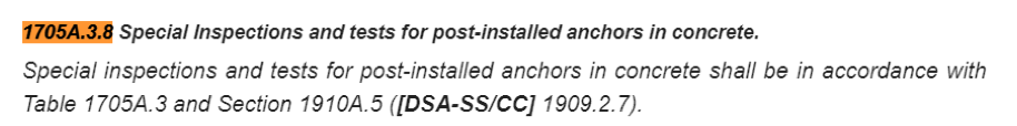
Testing procedures, including what to do if an anchor fails the proof load test and other such procedures, are clarified in sections 1910A.5.1 and 1910A.5.2 of the CBC. Test frequency is detailed in section 1910A.5.3 and is dependent of the intended use of the anchor. For structural anchors, all anchors (= 100%) shall be tested; for nonstructural anchors, only half (= 50%) require testing; and for sill plate anchorage, 10% require testing. Although these percentages are required by the CBC, in other nonessential structures proof loading a much lower percentage of post-installed anchors would be the generally accepted standard of practice. In my experience, anywhere from 10% to 25% of structural anchors would be tested unless extraordinary circumstances render more testing advisable. The specific test loads and percentage of anchors to be tested shall be listed on the contract documents. If any anchor fails the test load, more anchors shall be tested. This requirement needs to be shown on contract documents as well.
Determining Values for Proof Tension Loads — Two Approaches
Now, the fun part: Which value should be used for proof tension loads? We will start with the recommendations of the CBC “A” chapters, and then take a look at verbiage from evaluation reports.
California Building Code (CBC) — Tension Test Loading Requirements
When tension testing under the CBC is required as detailed above, there are two options and one limitation included in section 1910A.5.4 of CBC 2019. These are explained in depth below.
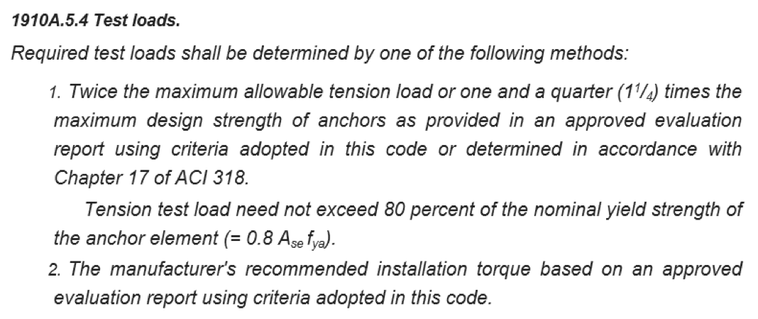 1. “Twice the maximum allowable tension load.”
Most concrete anchorage applications are no longer calculated using Allowable Load (or ASD) methodology. Instead, Strength Design values are calculated using ACI 318-19 chapter 17 methods. Most output from any current concrete anchorage design software is displayed in Strength Design format. Therefore, if this option is to be used, the Strength Design values should first be converted to an Allowable Load format, then multiplied by 2. Note that the calculated Strength Design value should include the effects of nearby concrete edges and closely spaced anchors, etc. The allowable tension load used is the capacity of the anchor, not the demand value.
2. “One and a quarter (1 1/4) times the maximum design strength of anchors as provided in an approved evaluation report using criteria adopted in this code or determined in accordance with chapter 17 of ACI 318.”
a. First, the “design strength” of a post-installed anchor into concrete is not included in either an ICC-ES or IAMPO-UES Evaluation Report. Although some reports include tables with the title “EXAMPLE … ANCHOR ALLOWABLE STRESS DESIGN TENSION VALUES FOR ILLUSTRATIVE PURPOSES,” those tables are typically for uncracked concrete, do not include edge distances, job-specific concrete strength, etc. and are not calculated for specific conditions common to most CBC projects. Therefore, I would not recommend using values in these tables to determine “maximum design strength of anchors.”
b. Per ACI 318, all post-installed anchor capacities shall be calculated in accordance with chapter 17. To determine the “maximum design strength” used for a test load, the following parameters are suggested:
i. Using an ACI 318-based anchor design software, calculate the capacity of each anchor failure mode considering all relevant factors: cracked concrete, seismic factors, concrete strength, concrete thickness, concrete edge distance, anchor diameter, length, phi factors, etc.
ii. Determine the governing (lowest) of all the calculated failure mode capacities. Recall, the load used is the capacity of the anchor, not the demand load on the anchor. Also note that the calculated design value is inclusive of the strength reduction “phi” factor (i.e. Design Strength = phi*Tn).
iii. Multiply this value by 1.25. This is the “test load” which shall be used for proof loading.
3. In all cases, the test load should be less than “80% of the nominal yield strength of the anchor element (= 0.8 x Asex fya).” For smaller anchors, ¼” to ½” in diameter, this nominal yield strength of the anchor often governs; whereas for larger anchors and for rebar (Gr. 60), this rarely governs. If 80% of the nominal yield strength (0.8 x Ase x fya) is lower than the test load determined by options 1 or 2, then it should be used as the test load instead.
Regarding the testing protocol, by and large, testing agencies rely upon field-testing standards of ASTM E3121/E3121M – 17 “Standard Test Methods for Field Testing of Anchors in Concrete or Masonry.” Though the protocol is followed as a whole, it is important to differentiate here the recommended testing methods in the CBC relative to statements made in evaluation reports.
 1. Hydraulic Ram Method
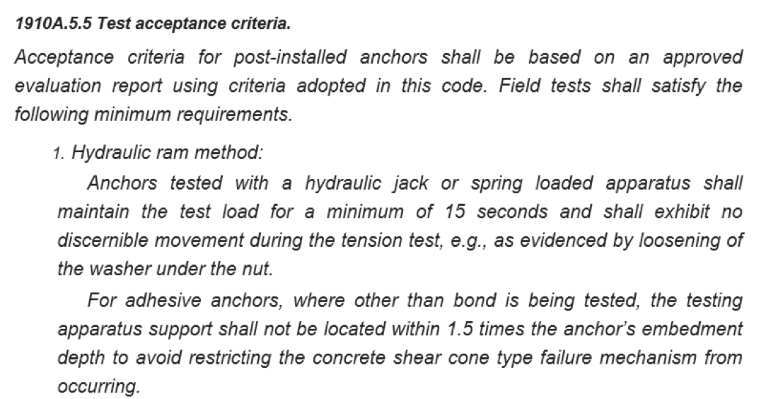
a. When using a hydraulic ram, the test load shall be maintained for 15 seconds and shall exhibit no discernable movement. A small initial load should be applied to the test rig before applying the test load so that the movement upon initial loading is not recorded.
b. The CBC “A” chapter section here states, “For adhesive anchors, where other than bond is being tested,” the testing apparatus shall meet certain requirements which are designated in ASTM E3121/E3121M-17 as “unconfined tests.” It is my professional opinion that for the majority of projects the bond strength is the very item which should be verified. Under no circumstances should the substrate or steel fail at the specified test load unless the EOR has determined that testing to failure is the desired result. Recall, the general idea of the proof load is to determine if the anchors were installed correctly. Incorrect adhesive anchor installation typically affects only the adhesive bond strength, not concrete or steel.
Evaluation Reports — Tension Test Loading Requirements:
Remember, continuous special inspection and proof loading are specifically required by ACI 318 and detailed in evaluation reports only for adhesive anchors horizontally and upwardly inclined (overhead installations), and also with sustained tension loads.
When required per the criteria above, the evaluation reports have this standard verbiage:
The first four items to be addressed may match what is in the “A” chapters of the CBC, although they are not required to be the same and are at the discretion of the Engineer of Record. Specifically, for standard CBC projects, most engineers will not require 100% of adhesive anchors taking sustained tension loads to be tested because of the expense to the owner. See above for further recommendations about percentage of anchors to be tested. Technically, the EOR could require that 0% (none) of the anchors had to be tested. Acceptable displacements are at the discretion of the EOR here as well as remedial action in the event of failure.
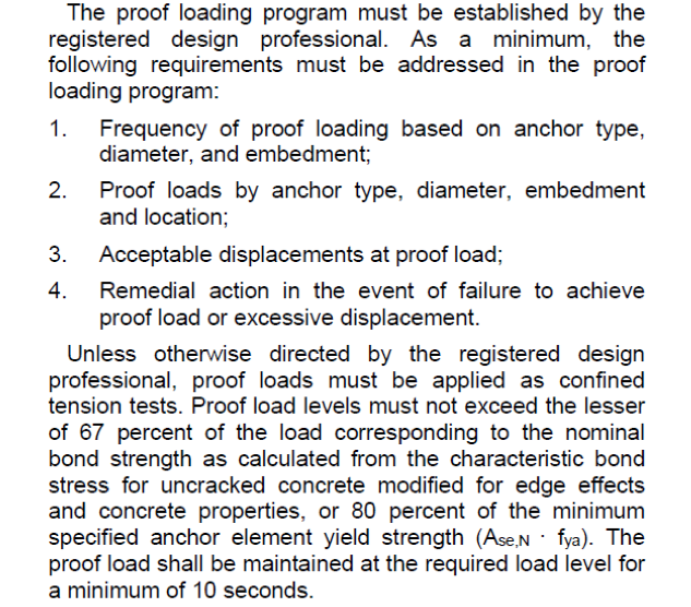
Notably directions to determine proof loads in evaluation reports differ from the CBC “A” chapter requirements. First, the evaluation reports recommend “confined” tension tests for all adhesive proof loading. This is in contrast to CBC section 1910A.5.5, unconfined test recommendations, but I agree with these confined tension test recommendations, since I believe the goal is to verify adhesive bond strength, not concrete strength.
Then, “proof load levels must not exceed the lesser of 67% of the load corresponding to the nominal bond strength as calculated from the characteristic bond stress for uncracked concrete modified for edge effects and concrete properties . . .”
From ACI 318-19 section 17.6.5.1, the nominal bond strength in tension, Na, of a single adhesive anchor
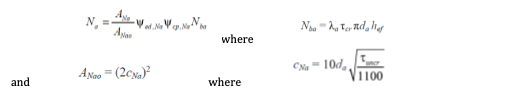
However, rather than go through the Na calculations by hand, we will utilize the values that engineers would typically be using, namely the results from an anchor designer for concrete software. In our case, we will look at output from Simpson’s free Anchor Designer™ for Concrete software.
Typical output values from a design software are Design Strengths, not Nominal Strengths.
Nominal Strengths are the Na values before the phi factors are applied. In other words, to get the Nominal Strength of the anchor, one would take the Design Strength and divide by the specific phi factor associated with that failure mode. The characteristic bond stress is the published bond stress in the evaluation report corresponding with either cracked concrete or uncracked concrete.
Evaluation Report Guidelines vs. CBC 2019 “A” Chapter Guidelines for Proof Loading Adhesive Anchors
Which method should we use? Well, let’s take a look at both of them. We’ll consider the Evaluation Report method first, since it’s fresh on the brain, and CBC A chapter method second.
Example 1: Determining the Proof Loading for Adhesive Anchors in Accordance with Evaluation Report Guidelines
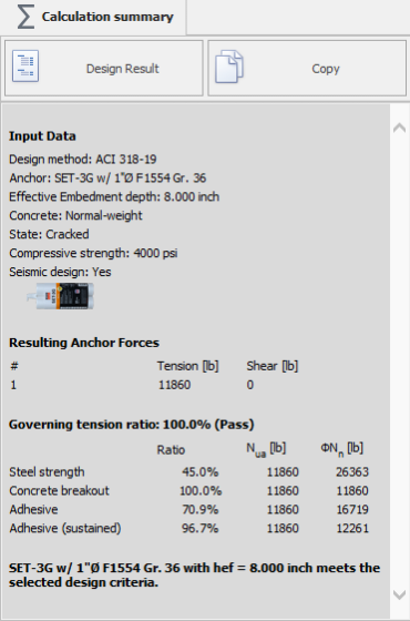
See our first example (below), where we’ve designed an anchor using SET-3G™ epoxy installed with a 1″diameter F1554, grade 36 threaded rod embedded 8″ into 4,000 psi concrete taking sustained tension loads. Design values in the output are shown for standard tension values as well as sustained (overhead) values.
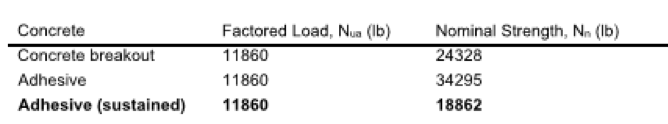
The Design Strength value = 11,860 lb., which was determined in accordance with cracked concrete, seismic loading, sustained loading, phi factors included. Note that even with 4,000 psi concrete, the concrete breakout governs the design strength, the adhesive strength does not govern.
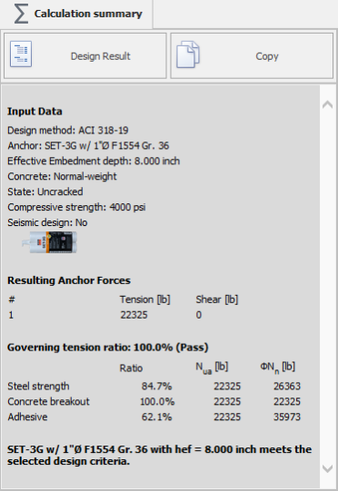
In order to determine the “nominal bond strength as calculated from the characteristic bond stress for uncracked concrete modified for edge effects and concrete properties” one would typically need to rerun the software calculation assuming uncracked concrete, non-seismic loading, and, it seems, unsustained loading, too.
Using the software, we determine that for anchors in this same configuration but with parameters assumed above (UCC, non-seismic, short-term load), the governing design strength is concrete breakout = 22,325 lb. However, the adhesive design value (i.e., capacity determined by UCC characteristic bond stress) is much higher at 35,973 lb. We’re not done yet, the values in the output are not Nominal Strengths, they are the Design Strengths.
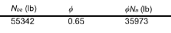
As stated above, Nominal Strengths are determined by dividing the Design Strengths by the associated phi factor (phi = 0.65 in this case). 35,973 lb. (Design adhesive Strength) x 1/0.65 (phi factor for concrete breakout) = 55,343 lb.
Alternatively, since I also have access to the software output file, the Nominal adhesive Strength is = 55,342 lb.
In accordance with ICC-ES tension test suggestions, the proof load is calculated as 0.67 x 55,343 lb. = 37,080 lb. Recall that the steel strength of the anchor shall be considered. All tension tests limit the test value to 80% of the yield strength of the anchor. The yield strength of the threaded rod is based on 36 ksi steel. In this case, for a 1″-diameter bolt, Ase is used; 0.606 x 36,000 x 0.80 = 17,453 lb. The yield strength of the steel governs the tension test value.
[I would like you to consider this further: If the yield strength did not govern, the tension test value of 37,080 lb. using ICC-ES proof load determination methods would be substantially higher than the Strength Design value of the anchor, 11,860 lb., by a factor of 3.13! Remember concrete governed the design strength, not the adhesive strength.]
Even though the yield strength of the steel governs this time, the originally determined proof load of 37,080 lb. was greater than the Strength Design value by a factor of 3.13. It is my opinion that this method seems inconsistent with the intent of the pull test and might result in concrete failure especially when anchors are close to the edge.
Example 2: Determining the Proof Load for Adhesive Anchors in Accordance with
CBC 2019 “A” Chapter Guidelines (also technically applies to CBC governed OSHPD 1R, 2 and 5, and DSA-SS/CC)
Alternatively, we will determine the tension test load for the same example in accordance with CBC “A” chapter recommendations of utilizing 1.25 x “Design Strength”. This method is from 1910A.5.4 of CBC 2019 highlighted earlier in this blog post. Typically, the Design Strength of anchors in high seismic areas of California would include cracked concrete, sustained loading factors (where appropriate), and seismic loading factors. Some would suggest excluding the phi factor when determining the Design Strength, because technically that value would be termed Nominal Strength, not Design Strength. We will explore both options below. The third option would be to assume uncracked concrete (UCC) bond stresses for Design Strength values. Using UCC bond stresses is partly covered in Example 1, but will be discussed here as option (c).
Based on the CBC “A” chapter methods, the tension test recommendation using Design Strengths would produce either:
Option (a) [Nominal] Design Strength (11,860 lb.) determined assuming cracked concrete, seismic loading, sustained loading x [1/0.65 (exclude phi factor for concrete breakout)] x 1.25 = 22,807 lb.
Option (b) Design Strength (11,860 lb.) determined assuming cracked concrete, seismic loading, sustained loading, phi factors included x 1.25 = 14,825 lb.
Option (c) Design Strength (19,785 lb.) determined assuming uncracked concrete (therefore no seismic loading), sustained loading, phi factors included x 1.25 = 24,731 lb.
Again, the steel strength of the anchor shall be considered. All tension tests limit the test value to 80% of the yield strength of the anchor. The calculated yield strength of the 36 ksi threaded rod = 17,453 lb. Note this value is not in the software output. The yield strength lower limit governs in cases (a) and (c) but not in (b).
In summary, suggested test load is either (a) and (c), 17,453 lb., or (b), 14,825 lb. The ratio of test load/Design Strength [d/c] for load option (a) and c) = 1.47, and for option (b) = 1.25.
If yielding was not considered, the factors would be (a) =1.92, (b) = 1.25, and (c) 2.08. In my opinion, the factors for options (a) and (b) (< 2.0) are more reasonable than that of option (c) or the factor calculated above using the evaluation service report methods that resulted in a factor of 3.13.
Just for kicks, let’s compare the test loads with the Nominal Strength of the anchor. Adhesive capacity for sustained tension controls the nominal value. From the software output, the governing Nominal Strength of the anchor in this example is 18,862 lb.
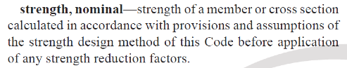
By definition (ACI 318-19 section 17.5.1.2), “Nominal strength for an anchor or anchor groups shall be based on design models that result in predictions of strength in substantial agreement with results of comprehensive tests.” It seems appropriate to use a test value closer to the Nominal Strength also defined in ACI 318 section, chapter 2 definitions as;
The tension test values determined in accordance with the CBC “A” chapter methods using Design Strengths (for all three CBC options considered) are lower than the Nominal Strength of the anchor: options (a) and (c) = 92.5%, and option (b) = 78.5%.
Recap
Remember: In the vast majority of cases, the intent of requiring a proof load is to determine the soundness of the anchor installation. The objective is not to load the anchor at such a high load that failure occurs within the steel, adhesive or the concrete. In my experience, a lower test value based on the CBC “A” chapter Design Strength method utilizing cracked concrete bond stresses (option b) seems to be both reliable and valid. Although options (a) and (c) yield results that are within the ballpark and could certainly be utilized. Recall, the building code often requires that omega level forces be applied to post-installed anchor applications, and therefore properly sized anchors should theoretically never see loads beyond their design strengths. In my experience, when proper installation methods are not followed, anchors will fail at even substantially lower tension test loads (vs. Design Strength). For deeply embedded adhesive anchors with adequate edge distances, when installed properly, failure of the adhesive or concrete should not occur at any load below the yield strength of the steel.
In summary: When tension proof load testing is determined to be appropriate, following guidelines from CBC A chapter, section 1910A.5.4, recommendations to utilize 1.25 x “Design Strength” seems to be more appropriate than the suggested proof loading determinations in evaluation reports. To determine the Design Strength value used in proof load calculations, all relevant factors would be included in the calculations, accounting for edge distances, anchor spacing, sustained loading factors, phi factors and seismic loading factors as deemed relevant. Cracked concrete bond stresses are often assumed for proof loading determination, although it would not be incorrect to utilize uncracked concrete bond stresses instead. In all cases, proof loads are limited to 80% of the yield strength of the steel.
If you need help with the Strength Design calculations, download the free Anchor Designer™ for Concrete software from Simpson Strong-Tie.
Note: This information has been compiled to the best of my ability and in accordance with the information included in the CBC 2019 code and standard verbiage in adhesive evaluation reports based on ICC-ES Acceptance Criteria 308. The intent of this article is that structural engineers might use this document as a guide, but in no case should this information supersede what is specified and previously approved on a set of Contract Documents.
