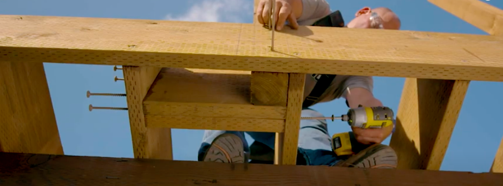
In this post, we follow up on our May webinar, Safer, Stronger Decks: Guard Post Connections, by answering some of the interesting questions raised by attendees.
During the webinar we discussed the minimum code requirements for railing posts and their connections, and the code-compliant connection methods: holdowns, deck tension ties, Strong-Drive® structural wood screws, and through-bolts. In case you couldn’t join our discussion, you can watch the on-demand webinar and earn PDH and CEU credits here.
As with our previous webinars, we ended with a Q&A session for the attendees. Our R&D engineers Scott Fischer and Rachel Holland answered as many questions as they could in the time allowed. Now we’re back to recap some of the commonly asked questions and their answers.
LOAD REQUIREMENTS
ASCE 4.5.1 requires that the 200 lb. point load be applied in any direction, not just away from the deck. How do you justify putting the tension tie holdown only at the top bolt attachment and not at the bottom bolt as well?
The IRC, IBC and ASCE 7 all require that the applied load at the top of the guard rail be considered in any direction. Specifically, 2018 IRC, Table R301.5, footnote d states that a single concentrated load (200 lb.) applied in any direction at any point along the top must be accounted for. ASCE 7, Section 4.5.1.1 uses the same wording, and is a reference when describing both the 200 lb. point load as well as the 50 lb. per–lineal–foot load on the top rail requirement in the 2018 IBC. This is referenced in IBC Section 1607.8.1. Note that in DCA6, Figures 24 and 25 only reference a top holdown and indicate that holdowns be installed in accordance with manufacturers’ instructions.
As it is possible that some local building officials may reason that the deck need only be designed and built to prevent individuals from falling off the deck and that addressing someone from falling “on” the deck may be of less safety concern, it’s important to understand what your building department requires. And though there has been discussion for several years to revise language in the code that would require only the outward and downward forces to be addressed, the wording of “any direction” is still the current code verbiage. Simpson Strong-Tie addresses this requirement in tech bulletin T-C-GRDRLPST20, in which we state that our details address an outward force on the guard rail and that an additional connector can be installed on the lower bolt to resist the inward force.
We’re discussing 200 lb. point load. But we’re also talking about some posts being 6 ft. o.c. Aren’t we supposed to resist 50 plf as well, or is the IRC not requiring that? At 6 ft. o.c., the point load would be 300 lb.
An important guideline to note here is that the IRC only requires the 200 lb. point load whereas the IBC requires both the point load and the line load. Specifically, the 200 lb. point load reference required by the 2018 IRC is in Table R301.5, while the 2018 IBC, Section 1607.8.1 requires the 50 plf line load and Section 1607.8.1.1 requires the 200 lb. point load. Note that ASCE 7-10, 4.5.1 states that the 50 plf load “need not act concurrently with the 200 lb. point load.” As we follow the load path, the 50 plf line load would be applied to ensure that the rail and infill are able to meet load carrying minimums and the 200 lb. point load is intended to ensure that the Guard Post is adequately connected to the deck structure. For jurisdictions following the IBC, at most times an engineer would be involved in the design and the structural calculations would determine which loading would govern. With that in mind, the IBC calculation would most likely show us that the 50 lb. line load would begin to control once the posts exceeded a spacing of around 4’ on center. In summary, only the 200 lb. point load is required for IRC designs, while both the point load and line load must be considered under the IBC and ASCE 7, although they’re not intended to be calculated cumulatively.
GUARD POST CONNECTION DETAILS
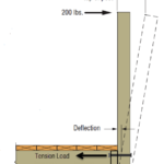
The resisting moment arm shall be measured between the centroids of the compression zone and the tensile zone. Is the diagram implying that the centroid of the compression zone is located at the bottom edge (tip) of the post/joist?
The resistance at the rim board connection would be in the form of a tension load at the top bolt, and then a triangular stress block on the compression side. The size of the compression block is dependent on the size of the rim board (say, 2×8 vs. 2×10) and the spacing of the two bolts. For the 2×8, the compression block would be smaller than that for the 2×10. Since the post is most often extended down to the bottom of that rim board, the compression block would begin at the bottom of the guard post or the bottom of rim location.
SST PRODUCT SOLUTIONS-SCREWS
Are the spacing and end distance requirements hard to meet with SDWS screws?
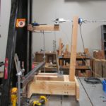
All of the SDWS fastener details for guard post installations shown in our Deck Connection and Fastening Guide are tested and rated based on a specific layout of fasteners.


