


One interesting part of being a field engineer for Simpson Strong-Tie is having the opportunity to see how different structural engineers may take different approaches to similar designs. We at Simpson Strong-Tie have come to appreciate these different approaches and embrace this phenomenon by providing multiple resources to aid in the completion of a design. This is very apparent when it comes to the design of post-installed anchors.
As many of you reading this blog know, the design requirements for anchoring in concrete to transmit structural loads are provided in ACI 318-19, Chapter 17 – Anchoring to Concrete. The equations featured in Ch. 17 of ACI 318 are plentiful and lengthy, making it a tedious task for any structural engineer performing hand calculations in accordance with this standard. In response, Simpson Strong-Tie has created multiple software solutions to aid in the design of these anchors, such as the Anchor Designer™ for Concrete Software and Post-to-Foundation Designer. These two software platforms are a great resource for any structural engineer to have. However, for single-anchor design conditions, some engineers still prefer allowable load tables to determine the capacity and required embedment of post-installed anchors.
Listening to the needs of our engineering customers, Simpson Strong-Tie has produced both Allowable Stress Design and Strength Design load tables for many of our high-strength post-installed anchoring solutions. This blog post will introduce these anchor allowable load tables in the form of our Technical Engineering Bulletin (TEB) document for anchors. Additionally we will include design examples utilizing the load tables and highlight important information to note while using these load tables.
The three most popular Technical Bulletins for Anchor Design support both our adhesive and mechanical post-installed anchor solutions. These comprise the following bulletins:
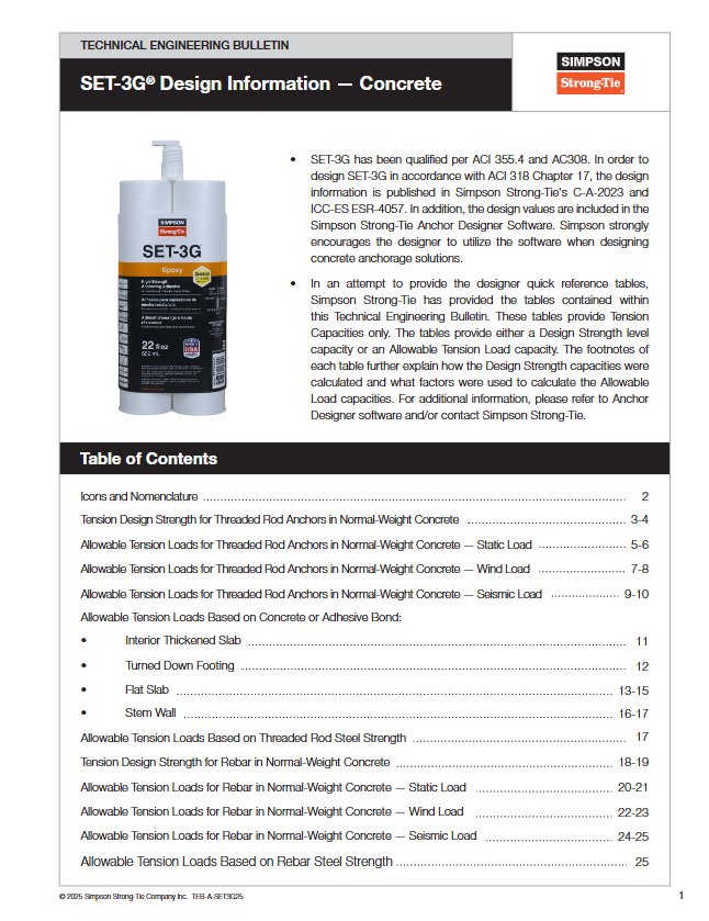
- TEB-A-SET3G25 – SET-3G™ Design Information — Concrete (SET-3G high-strength epoxy adhesive)
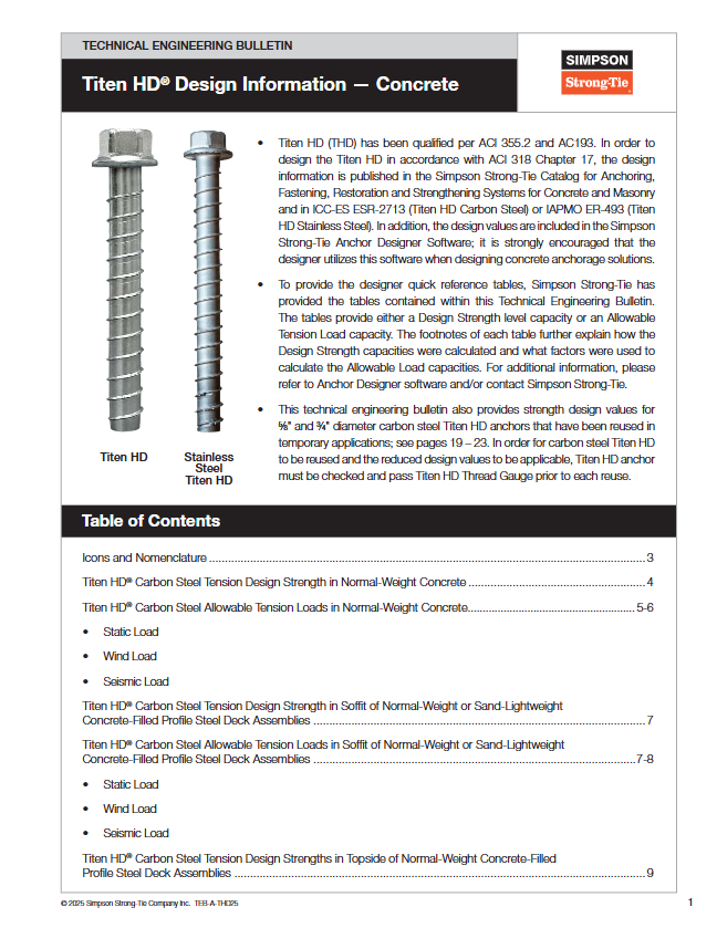
TEB-A-THD25 — Technical Bulletin - TEB-A-THD25 – Titen HD® Design Information — Concrete (Titen HD Heavy-duty screw anchor)
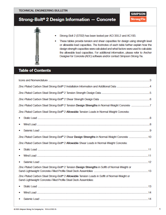
TEB-A-STB2-25 — Technical Bulletin - TEB-A-STB2-25 – Strong-Bolt® 2 Design Information — Concrete (Strong-Bolt 2 wedge anchor)


Bonus TEB!
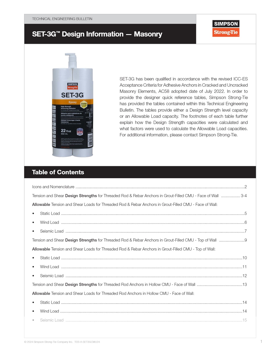
- TEB-A-SET3GCMU24 – SET-3G Design Information for Cracked and Uncracked Masonry Elements. Check out our in-depth blog post, Overview of the Strength-Based Cracked and Uncracked Masonry Design Standards for Adhesive Anchors, for further information.
There are similarities that you will find between all TEB documents and as well as specific conditions unique for each product.
Load tables that you will find in all TEB documents include the following:
- Tension Design Strength in Normal-Weight Concrete. Tension Design Strength is also known as Strength Design, which uses the strength reduction factor, ø, based on using a load combination from ACI 318-19 Section 5.3.
- Allowable Tension Loads in Normal-Weight Concrete for Static, Wind and Seismic loads. Loads provided in these Allowable Tension Load tables are based on tension design strengths that are converted to allowable tension loads using a conversion factor that is based upon a load combination dependent on the loading condition (static, wind, or seismic).
Some specific conditions unique to each product include, but are not limited to:
- Shear Design Strengths and Allowable Shear Loads for both the Titen HD® and Strong-Bolt® 2 mechanical anchors.
- Load tables for both the soffit and topside of normal-weight concrete-filled profile steel deck assemblies for the Titen HD heavy-duty screw anchor.
- Shear Design Strengths and Allowable Shear Loads for 1/4″- and 3/8″-diameter Titen HD anchors with 1″ Nominal Embedment Depth.
Important Notes for Using Anchor Load Tables
Certain design assumptions and conditions are needed to produce these anchor load tables. It’s important to note that these design assumptions and conditions are stated in the load table icons on page 2 of the TEBs and in the table footnotes for each corresponding table. The footnotes of each table further explain how the Design Strength (Strength Design) capacities were calculated and what factors were used to calculate the Allowable Load capacities. We recommend that designers review all footnotes when using any of the load tables. Listed below are some common notes that exist on multiple tables.
- Tabulated values are for a single anchor with no influence of another anchor. In other words, these tables would not be appropriate for designing anchors in a group configuration due to the effect on concrete breakout, pullout, and adhesive bond strength. For group anchor conditions, we recommend that designers use the Anchor Designer™ for Concrete software for accurate design results.
- Interpolation between embedment depths is not permitted.
- This note is for adhesive anchors only: Designer is to select the lower value from the Design Strength or Allowable Load table and its corresponding steel strength for strength design or allowable tension load. In other words, the Design Strength and Allowable Load tables take into account the concrete breakout strength, pullout strength, side-face blowout strength, and adhesive bond strength; however, steel strength in tension needs to be checked separately using the tables referenced in the TEB.
Design Example
Now that we’ve highlighted the information available and important footnotes in the TEB documents, let’s go through some design examples showing how quickly information can be pulled from these resources.
Design Example 1: Allowable Tension Loads for SET-3G™ Anchoring Adhesive with Threaded Rod in Normal-Weight Concrete
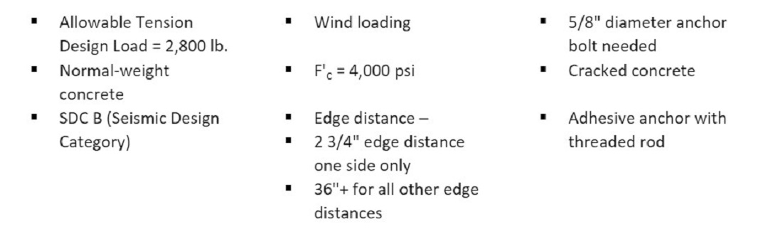
Design Example 1 shall consider post-installed adhesive anchorage for a typical holdown connection. The required allowable tension design load that needs to be achieved is 2,800 lb. resulting from wind loading. In this example, the engineer has selected the HDUE3-SDS3 holdown which accommodates a 5/8″-diameter anchor bolt. The other design conditions are shown below:
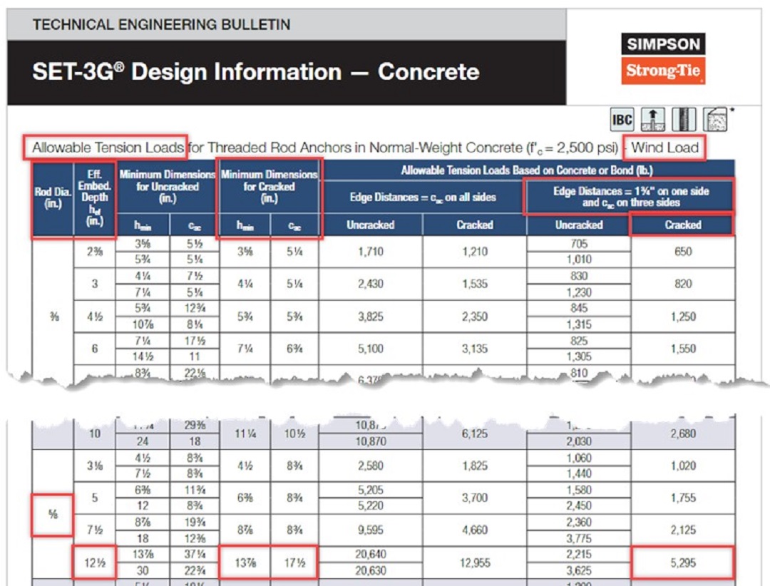
Equipped with these design criteria, we can quickly reference the SET-3G™ Design Information – Concrete TEB. Since we are looking for Allowable Loads and the loading condition is from wind loading, we will reference the “Allowable Tension Loads for Threaded Rod Anchors in Normal-Weight Concrete – Wind Load” on pages 7-8.
As shown in the image below, you can use the referenced table to select an effective embedment depth of 12 1/2″ for a 5/8″-diameter threaded rod, providing an Allowable Tension Load of 5,295 lb., which exceeds our design load of 2,800 lb. for this example.
Please note that for this design example we have pulled from the load column that corresponds with “edge distances = 1 3/4″ on one side and cac on three sides.” It’s worth noting that our actual edge distance is 2 3/4“; however, the other column choice in this table references “edge distances = cac on all sides,” which a 2 3/4″ edge distance does not meet. Therefore, we are left with making the conservative choice of using the edge distances = 1 3/4″ column. In addition, for this design table we do not benefit from any additional load capacity based upon the higher compressive strength of the concrete since the tables are created using f’c = 2,500 psi concrete and our example has f’c = 4,000 psi concrete.

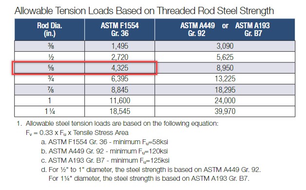
We are not done with our checks, however. As mentioned in the “Important Notes” section above, we need to confirm the allowable tension load based on steel strength before finalizing our design. Page 17 in the TEB-A-SET3G25 provides a load chart of “Allowable Tension Loads Based on Threaded Rod Steel Strength.” From this chart we can see that a 5/8″-diameter ASTM F1554 Gr. 36 threaded rod will provide an allowable tension load of 4,325 lb.. While this value is smaller than our adhesive allowable strength, it does exceed the design load of 2,800 lb. Therefore, there isn’t a need to use a higher-strength rod.
While this was a quick and easy way to produce a working embedment depth with SET-3G adhesive, it does provide a somewhat conservative design given that allowable strength greatly exceeds the design load. If you are curious whether there’s a more efficient design using these TEB documents, then please read on to Design Example 2!
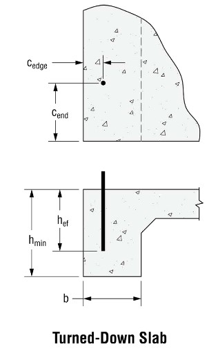
Design Example 2: Allowable Tension Loads for SET-3G™ with Turned-Down Footing
For Design Example 2, we’ll use the same loading condition. This time, however, we’ll also assume that we’re designing with a turned-down footing (See image below). This turned-down footing information allows us to utilize another table in the TEB document, one that is specifically suited for our example.
Please note that there are multiple tables in each of the TEB documents addressing a variety of anchorage conditions.
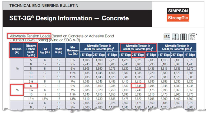
Because this design example features 4,000 psi concrete with a wind-controlled design load, we’ll use the load table “Allowable Tension Loads Based on Concrete or Adhesive Bond – Turned-Down Footing (Wind or SDC A-B)” found on page 12 of the TEB document.
One thing to notice in this turned-down footing load table is that the geometry conditions are much more specific. This table by chance matches our design application, and therefore we’re able to use its load values, which should give a more precise result compared to the more general allowable tension load tables.
Immediately you’ll notice that we can utilize this table to achieve a satisfactory allowable tension load with a shallower embedment. An effective embedment depth of 8″ for a 5/8″-diameter threaded rod for 4,000 psi Concrete and a 2 3/4″ edge distance per the turned-down footing detail below will provide an allowable tension load of 3,645 lb., which exceeds our design load of 2,800 lb. for this example.
Again, we would need to confirm that the allowable steel strength is sufficient, a step we already completed in Design Example 1 for the 5/8″-diameter rod.
Conclusion
It’s apparent based on these two design examples that there are multiple ways to use the design tables included in Simpson Strong-Tie® Technical Bulletins for anchor design. Some takeaways are that it’s always important to confirm that the information contained in the TEBs is being followed correctly by using the appropriate table and carefully examining the conditions and footnotes in the tables to ensure they are appropriate for each given design condition.
Having these design tables offers a quick and efficient way to design anchoring solutions in accordance with the appropriate design standards. Happy Anchor Designing!
