

Engineers spend much of their career designing and detailing main structural members which are exposed to significant structural loads. An experienced engineer will often master this type of design and excel at detailing an efficient building system. However, these same savvy engineers are sometimes left scratching their heads when tasked with providing a clean and simple design for attaching components such as cabinets, shelves or handrails to interior finish. Simpson Strong-Tie’s versatile new WBAC Wood Backing Steel Connector provides the engineer with a fully tested design solution that efficiently and easily attaches wood backing members for heavy wall hangings.
This blog post will cover a specific design example on how to utilize the WBAC Allowable Loads table to properly design an adequate connection for wood backing members. Before we dive into the design example, let’s first go over some of the features of the WBAC that make this connection ideal for the contractor as well as the engineer.

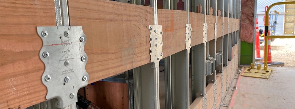
Many installers prefer to attach nonstructural equipment through drywall into a wood member. The WBAC wood backing steel connector is the ideal solution for connecting wood backing (commonly referred to as wood blocking) to cold-formed steel (CFS) studs. Perfect for cabinets, shelves, handrails, heavy wall hangings, and more, this versatile connector installs easily and provides tested strength.
Key Features for Simple and Quick Installation:
- Prepunched holes in the WBAC allow the same screw type (#8-18 modified truss head screw) to be used for fastening to both CFS stud and wood backing members
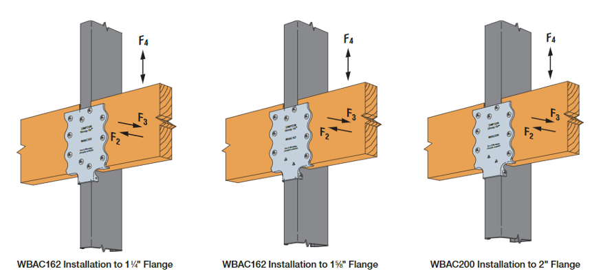
- Accommodates a wide range of CFS stud flanges, including 1 1/4″, 1 3/8″, 1 5/8″, and 2″ widths
- Applicable to any CFS stud spacing (e.g. 12″, 16″, or 24″ spacing)
- Sight lines to guide installation alignment
- Integrated bottom tabs on WBAC connector allow wood backing to rest on connector for easier installation
Key Features for Extra Strength and Stiffness:
- Fully assembly-tested strength and stiffness in accordance with ICC-ES AC261
- Unique rolled support bottom tabs provide extra strength and stiffness while minimizing material gauge thickness requirements
- Published allowable loads for strength and deflection limits
Being an engineer by trade, I can’t help but highlight the fact that the WBAC has been fully assembly tested for strength and stiffness. What this means is that the WBAC has been tested in its actual field construction assembly of being fastened to a CFS stud and wood backing member with the approved fasteners. Most importantly, this assembly testing reveals the real failure mechanism for the connector. This allows Simpson Strong-Tie to fully understand the connector’s behavior, which leads to an optimized engineering design that provides extra strength and stiffness.
WBAC Load Tables
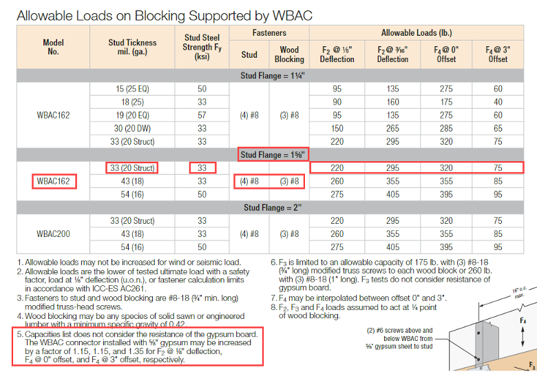
A design featuring the WBAC wood backing steel connector can easily be completed by utilizing the published allowable loads found in the Allowable Loads on Blocking Supported by WBAC table accessible on the WBAC product website or the WBAC product flyer C-CF-2023 p.160-161. Let’s start by going over some background information regarding the load table.
The table is separated by WBAC model number and associated stud flange width (1 1/4″, 1 5/8″, and 2″).
It’s worth noting that the WBAC162 model is capable of installation onto a 1 3/8″ stud flange, although no mention of a 1 3/8″ stud flange is made in the Allowable Load table. For 1 3/8″ stud flanges, the associated allowable loads published for 1 1/4″ stud flanges are acceptable to use because the same WBAC162 model and fastener pattern are used for both 1 1/4″ and 1 3/8″ stud flange widths.
There are three load directions given in the table. Lateral loads F2 and F3 are defined as out-of-page and in-to-page loading directions, respectively. Load direction F4 accounts for both downward and upward directions.
The F2 load direction capacity provides capacity in the F2 direction at 1/8″ and 3/16″ deflection. The F4 load capacity is governed by the specified load offset ranging from 0″ to 3″, with allowance for interpolation for offset conditions between 0″ and 3″. The offset dimension is defined as the distance from the point of the load to the face of the drywall or gypsum wallboard surface.
Speaking of gypsum board, Simpson Strong-Tie recently performed assembly tests of the WBAC support with 5/8″gypsum board installed over the WBAC blocking supported system. The tests revealed a load increase to the WBAC system due to the increase rigidity of the system when including the fastened gypsum board. Per footnote 5 on the WBAC Allowable Loads table, the WBAC connector installed with 5/8″ gypsum and referenced screw attachments may be increased by a factor of 1.15, 1.15, and 1.35 for F2 @ 1/8″ deflection, F4 @ 0″ offset, and F4 @ 3″ offset, respectively.
Lastly, it’s worth discussing footnote 8 on the WBAC Allowable Loads table, which states that F2, F3, and F4 loads are assumed to act at a 1/4 point of wood blocking. It is common to see many other backing products available on the market that publish allowable loads on the basis that the load is located directly in the middle span of the wood blocking. This design approach assumes that the load is equally distributed to both end attachment points of the wood blocking. If a load is located outside of the blocking mid-point, then further investigation is required by the designer. Conversely, the allowable loads associated with the WBAC assume that the loading point of a wood backing will likely occur outside the midpoint of the span. This allows the designer to consider a wider range of attachment locations along the length of a wood backing before requiring further investigation.
Equipped with this baseline knowledge, let’s run through a design example using the Allowable Loads table available in the C-CF-2023 p.160-161 Flier.
Design Example — Hospital Wall-Mounted Equipment Support
Our design example will feature medical equipment that is wall mounted, which is a common placement for such equipment in hospital construction settings. The equipment will attach directly to wood backing, which will in turn be attached to CFS studs using the WBAC connector. In this example, we will identify how to properly use the Allowable Loads table and clear up any questions that may typically arise.
Loading Information:
The “Medical Equipment” unit shown in the figure below is being attached to the wall at four different points. For this example, these points happen to occur at locations between the CFS studs, thus requiring wood backing as an attachment point for the equipment. The loading information has been provided by the equipment manufacturer and has been shown in the figure below.
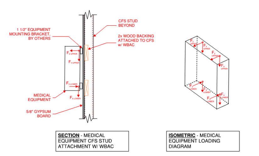
We are going to focus on the upper and lower anchoring points. Let us first take a closer look at the upper anchoring point. As you can see, the top anchoring point has associated horizontal (F2 direction) and vertical-downward (F4 direction) forces.
The upper anchoring point of the equipment attachment to the wood backing occurs at the quarter point along the wood backing span.
For this example, the wood-backing-to-CFS-stud attachment points would experience an applied horizontal load in the F2 direction equal to 130 pounds (lb.). The F4 downward force is listed as 110 lb. with a 1 1/2” offset. The offset condition is created by the thickness of a 1 1/2″ mounting bracket preattached to the medical equipment. Offset conditions will vary from project to project based on the anchoring attachment.
Once we’ve established our loads, the next step is to reference the available WBAC Allowable Loads tables.
For the purpose of our design example, it will be assumed that a 33 mil (20 ga) structural stud with a 1 5/8″ stud flange width and 33 ksi steel strength has already been selected as the stud size. The studs are also sheathed with 5/8″ gypsum board (this allows for an increase in loads per footnote 5 in the Allowable Loads on Blocking Supported by WBAC table). Based upon this stud flange width, we can see that the WBAC162 model number is appropriate for this application. Reviewing the load table we can quickly gather the necessary design information as listed below:
Allowable Loads:
F2 @ 1/8″ Deflection: 220 lb.
F2 @ 3/16″ Deflection: 295 lb.
F4 @ 0″ Offset: 320 lb.
F4 @ 3″ Offset: 75 lb.
As mentioned in the design parameters above, the stud assembly will be sheathed with a 5/8″ gypsum board, which then allows us to utilize the load increase factor according to footnote 5.
Allowable Loads with Gypsum Board Increase Factor:
F2 @ 1/8″ Deflection: 253 lb.
F2 @ 3/16″ Deflection: 295 lb.
F4 @ 0″ Offset: 368 lb.
F4 @ 3″ Offset: 101 lb.
Let’s first confirm that the horizontal, F2, loading direction is acceptable.
F2 load demand: 130 lb.
WBAC162 F2 allowable load: 253 lb. with 1/8″ deflection
The demand capacity ratio (DCR) for this application is an acceptable 0.51, below the maximum 1.0 allowable ratio.
Please note that this allowable load is based upon limiting the horizontal deflection of the WBAC connector to 1/8″ of movement. If it was acceptable to increase this allowable deflection limit to 3/16″, we could take advantage of the higher allowable loads corresponding to the larger deflection.
Next, let’s take a closer look at the downward, F4, loading direction.
F4 load demand: 110 lb.
For this application, the F4 load is being applied with an offset dimension of 1 1/2″. Per the WBAC Allowable Loadstable, footnote 7, F4 may be interpolated for offset conditions between 0″ and 3″. Using the published F4 values, we can linearly interpolate a F4 load corresponding with a 1 1/2″ offset equaling 235 lb.
The DCR for this application is an acceptable 0.47, below the maximum 1.0 allowable ratio.
The last design step for the upper attachment point is to consider the interaction equation, since this connector is being loaded simultaneously in more than one direction. For the WBAC connector, it’s appropriate to use the following equation:
Design Horizontal Load / Allowable Horizontal Load + Design Vertical Load / Allowable Vertical Load < 1.0.
Please note that it is acceptable to utilize the higher horizontal allowable load associated with F2 @ 3/16″ deflection since the interaction equation is checking the connector against failure. While the load associated with F2 @ 3/16″deflection isn’t truly the load corresponding to the connector failure, it does provide a load closer to the failure load when compared to F2 @ 1/8″.
Design Example Interaction Unity Equation:
130 lb. / 295 lb. (F2 @ 3/16″ deflection) + 110 lb. / 235 lb. = 0.91 < 1.0 – Acceptable!
No further load investigation is necessary for the upper attachment point.
Lastly, let’s review the attachment at the base of the equipment. The loads present at the base consist of a F4downward, which is equal to the magnitude at the top attachment, and an F3 horizontal load oriented into the plane of the wall. The magnitude of the applied F3 load equals 130 lb., which is the equal and opposite force of the F2 load at the top attachment.
The F4 allowable capacity has already been established in the example above.
To establish the F3 allowable load, reference WBAC Allowable Loads footnote 6: “F3 is limited to an allowable capacity of 175 lb. with (3) #8-18 (3/4″-long) modified truss screws to each wood block or 260 lb. with (3) #8-18 (1″ long). F3 tests do not consider resistance of gypsum board.”
To ensure that the interaction unity equation is met, the design will utilize (3) #8-18 (1″-long) modified truss screws with a 260 lb. F3 allowable load. With a F3 load demand – 130 lb., the DCR for the F3 load is an acceptable 0.50.
The corresponding interaction unity equation for the lower attachment point is an acceptable 0.97 (130 lb. / 260 lb. + 110 lb. / 235 lb. = 0.97).
And that’s how quick and easy it is to design the WBAC wood backing steel connector! The WBAC connector now provides engineers with a versatile and efficient solution for supporting wood backing to tackle a wide variety of interior finish attachments.
