Not all post-installed mechanical anchors are created equal. There are key differences between screw and expansion anchor types — differences that include how they gain their holding strength, installation requirements, and overall anchor performance. In the following post, field engineers Todd Hamilton, Chris Johnson and Derek Gilbert compare the two anchor types.
Post–installed structural mechanical anchors are generally categorized as either expansion anchors (aka wedge anchors) or screw anchors. These types of anchors are used after concrete is cured or CMU is placed and offer quick and easy installation in a wide range of applications. What’s the difference? When should you specify one rather than the other? This blog post will help you understand the similarities and differences and guide you in selecting the best anchor for your specific project need.
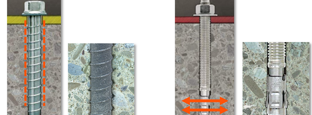
By definition, a screw anchor is a threaded mechanical fastener placed in a predrilled hole (see Figure 1). The anchor derives its tensile holding strength from the mechanical interlock of the fastener threads with the grooves cut into the concrete during anchor installation (see Figure 2). Screw anchors are tested and evaluated in accordance with ACI 355.2 and ICC-ES AC193 for concrete (cracked and uncracked) and ICC-ES AC106 for masonry (hollow and grout filled). In practice, screw anchors are used across a variety of structural applications and industries to anchor items such as sill plates, threaded rod uplift systems, shearwall bottom plates, wood and cold-formed steel holdowns, column/post baseplates, ledgers, rigid kneewalls, racking systems, railings, mechanical equipment, electrical conduits, cable trays and piping supports.
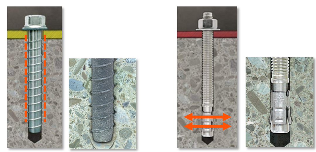
In contrast, a wedge-type expansion anchor consists of a steel stud with nut and washer, threaded on the top end with a formed tapered mandrel on the opposite end around which an expansion clip is positioned (see Figures 1 and 2). The anchor is installed in a predrilled hole and set by tightening the nut to a specified torque, thereby causing the expansion clip to expand through deformation or torque over the tapered mandrel to engage the base material and create a frictional connection (see Figure 2). A wedge anchor may also be referred to as a torque-controlled expansion anchor. Expansion anchors are also evaluated in accordance with ACI 355.2 and AC193 for concrete (cracked and uncracked) but ICC-ES AC01 for masonry (grout filled only). Typical industry applications for expansion anchors may include: column/post baseplates, ledgers, stair stringers, rigid kneewalls, racking, fire protection pipe attachments (UL listed for vibration), and mechanical-electrical-plumbing (MEP) bracing supports (UL listed for vibration).
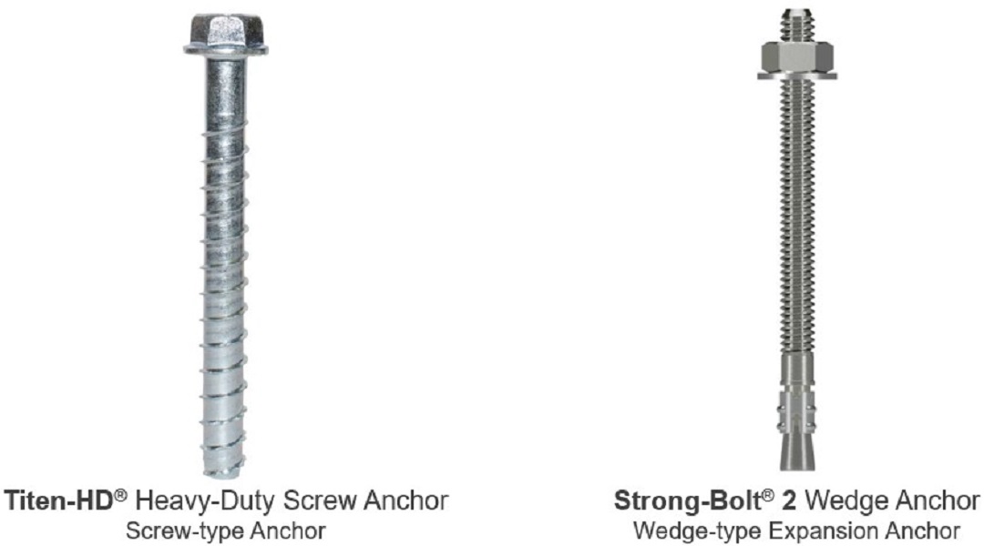
Simpson Strong-Tie offers a wide variety of code-listed screw- and expansion-type anchor products in multiple material types (carbon and SS) and coatings (zinc plated or galvanized) — see Figure 3. This blog post focuses on the high-strength Titen HD® (THD) concrete and masonry screw anchor and the Strong-Bolt® 2 (STB2) wedge-type expansion anchor.

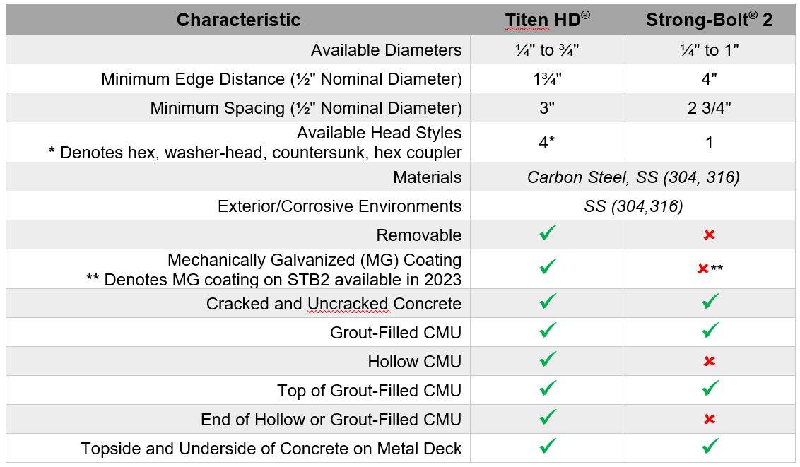
To get started, Table 1 presents similarities and differences between these two anchors across several characteristics. Most notably, the THD has a smaller minimum edge distance and spacing, has the ability to be removed, can be installed in both hollow and grouted CMU and comes in four different head styles (hex, washer head, countersunk, and hex coupler).
Since the STB2 expansion anchor clip exerts an outward radial force into the concrete (see Figure 2), it requires a larger minimum edge distance and spacing compared to a screw anchor. Figure 4 shows the relationship between anchor edge distance and spacing for ½”-diameter sizes of both the THD and the STB2 in concrete. For the STB2, spacing and edge distance combinations must fall on or above and to the right of the blue line shown. For example, for an edge distance, c, of 10″ (black dashed line in Figure 4), the STB2 cannot be spaced less than ~3″. By contrast the THD can be located at a minimum edge distance, c, of 1.75″, and be spaced no less than 3″.
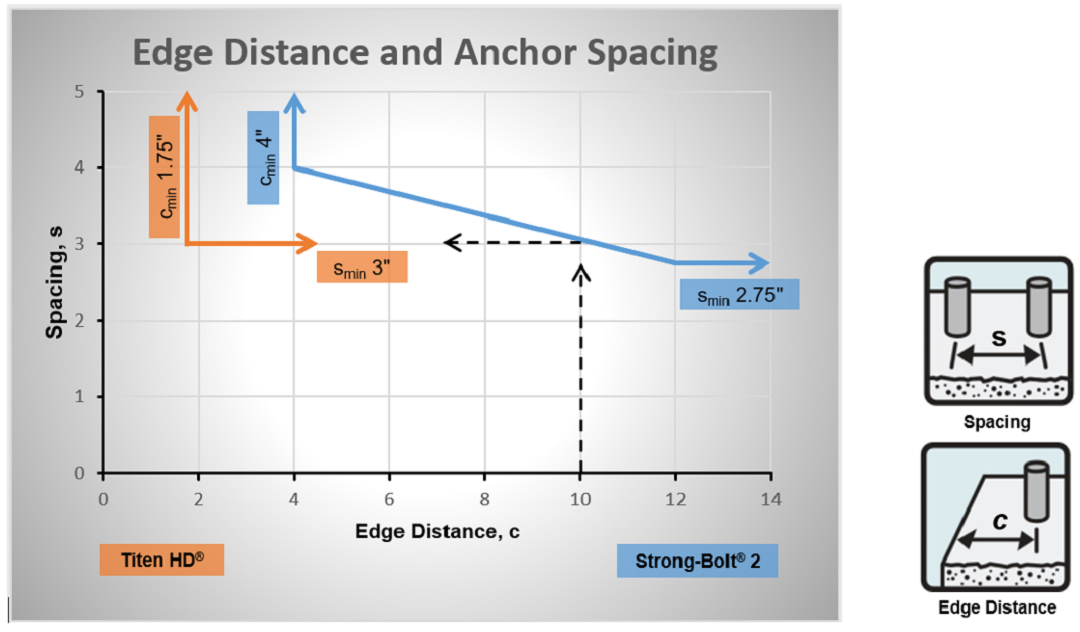
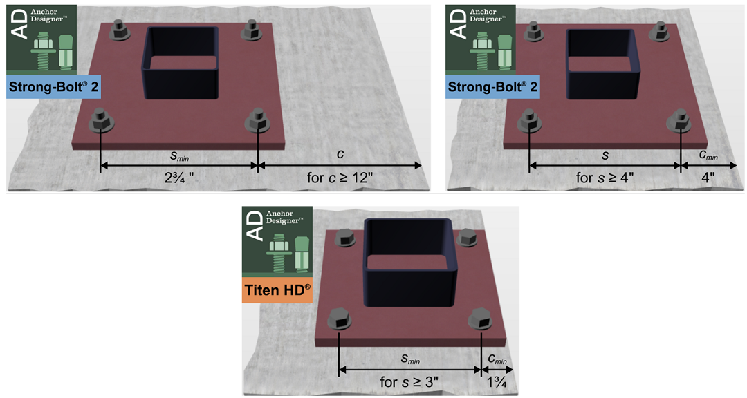
Figure 5 illustrates a typical column base plate and anchor detail for two conditions: minimum edge distance (cmin) and minimum spacing (smin). If the STB2 is located 4″ from the concrete edge (as shown in the detail to the right), adjacent anchor spacing can be no less than 4″ on center. If the STB2 is located 12″ from a concrete edge (as shown in the image to the left), adjacent anchor spacing can be no less than 2¾” on center. The THD can be located 1 ¾” from a concrete edge and adjacent anchors spaced no less than 3″ on center. As seen in Figures 4 and 5, edge distance and spacing requirements, along with design loads and concrete substrate geometry (e.g., slab, stem/foundation wall, pier/pilaster) have the ability to impact the column base plate size, concrete element geometry, and anchor spacing. If the existing concrete element geometry is narrow or requires small concrete edge distance, the THD and its lower minimum edge distance may meet the design constraints.
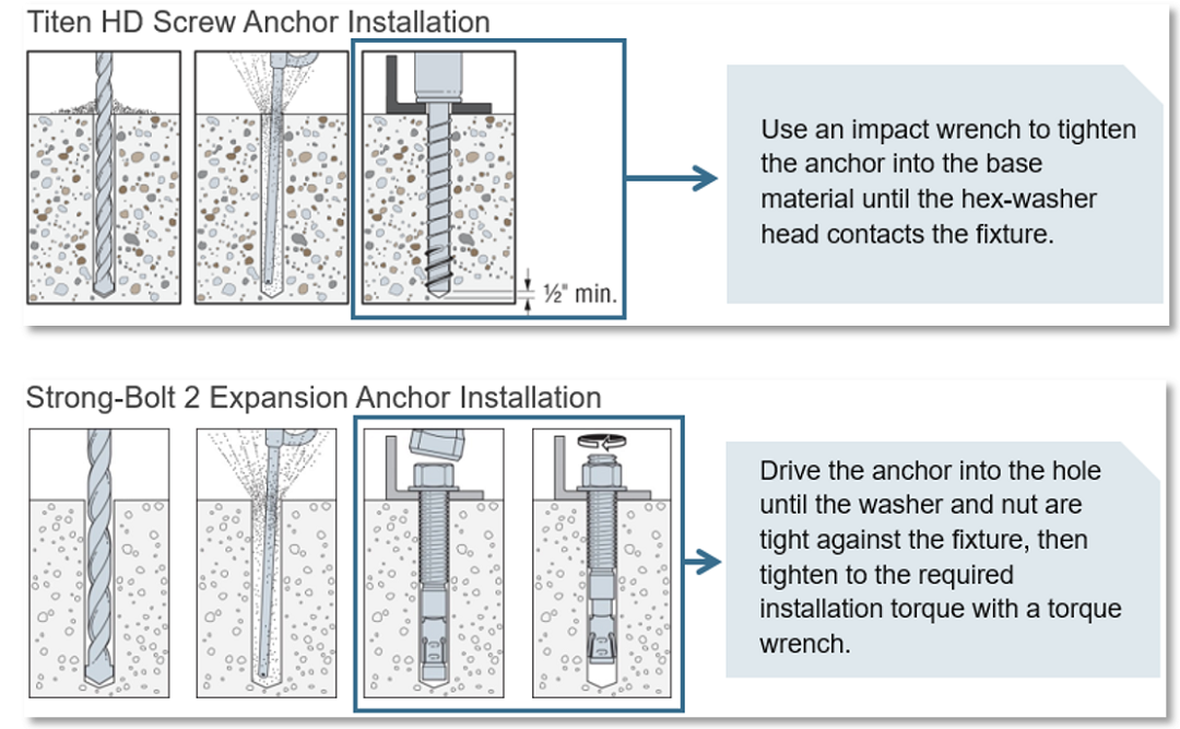
With regard to the anchor installation sequence, Table 2 and Figure 6 describe the installation differences between the two anchors. In this comparison, the THD has fewer overall installation steps, does not require a specific installation torque, and can be snug tightened with a hand wrench or impact driver. In addition, the THD does not need to be hammer driven into the drilled hole. Lastly, the overall installation time of a THD is about five times faster than that of a wedge-type anchor.

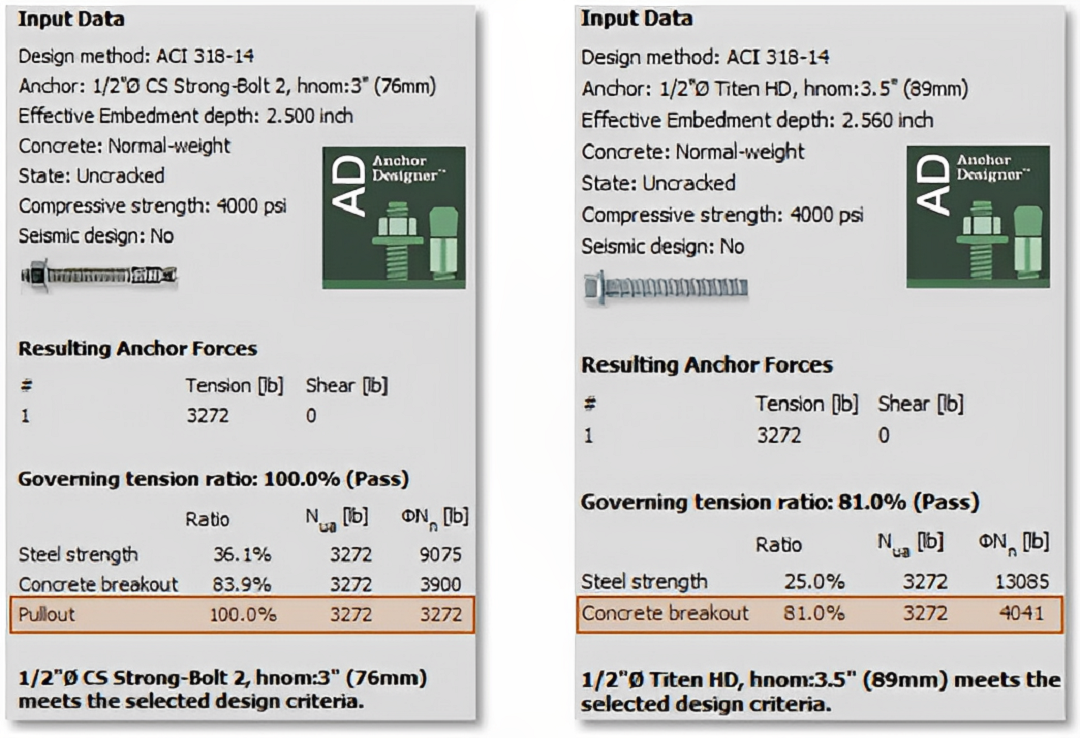
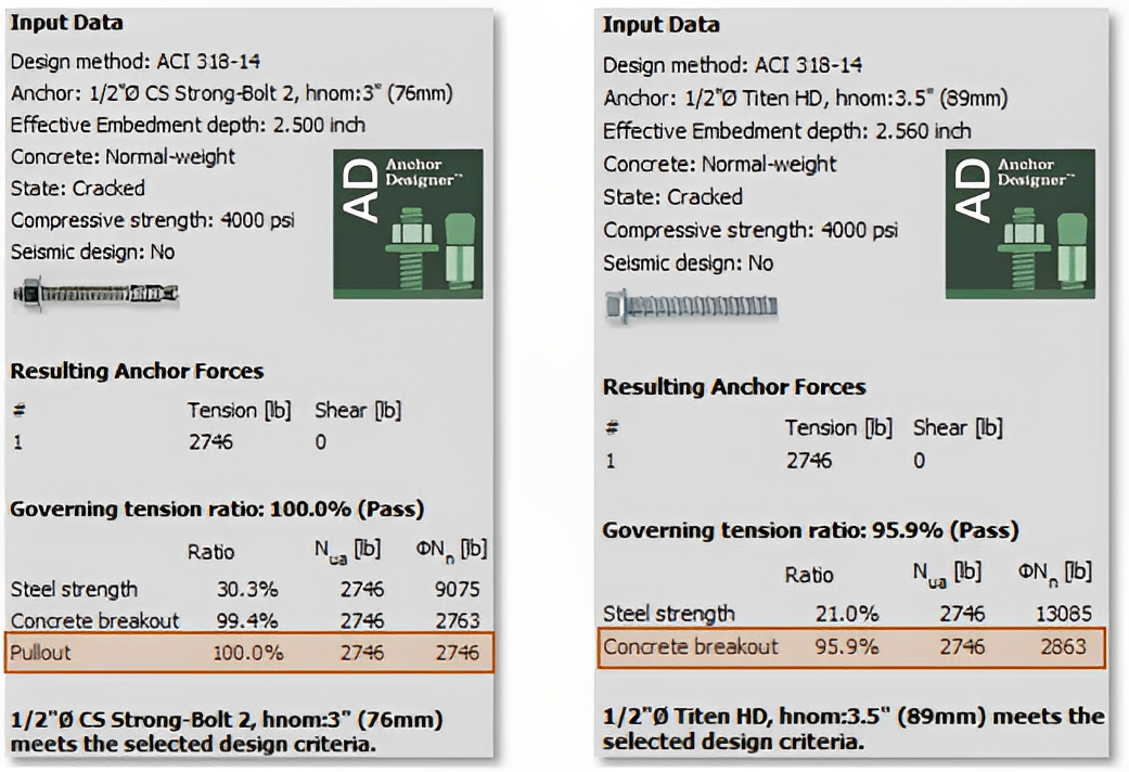
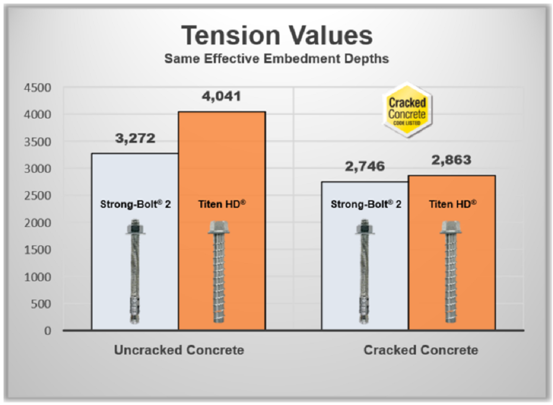
In a performance comparison, Figures 7 and 8 display the tension design output values for ½”-diameter anchors in uncracked and cracked concrete (4,000 psi) with the same effective embedment depths using the Simpson Strong-Tie Anchor Designer software. Figure 9 displays the governing tension design results as a bar chart. The STB2 capacity is controlled by the pullout failure mode, whereas concrete breakout was the THD controlling limit state. Collectively, these results indicate that for the same effective embedment (~2.5″) and diameter, the THD has about a 20% increased capacity in uncracked concrete and a smaller 5% increased capacity in cracked concrete. This specific design example assumes a single anchor located away from a concrete edge condition. Therefore, there was no capacity reduction due to edge distance, spacing or anchor group conditions. Note, the total number of anchors, embedment depth, edge distance, and spacing among other factors need consideration when comparing different anchors and design results.
It is important to understand the advantages and disadvantages of each type of mechanical anchor for a given project specific application. Screw and expansion anchors have distinct installation, substrate, edge distance, spacing, and performance requirements that will fit different project applications and field conditions. The Titen HD® Heavy-Duty screw anchor saves on overall installation time, offers greater application flexibility, and is less susceptible to installation error. On the other hand, the Strong-Bolt® 2 wedge-type expansion anchor has a lower product cost but requires additional installation time and larger edge distances and spacing. Collectively, these code-listed mechanical anchors help construction professionals design and build safer, stronger structures more efficiently.
Visit strongtie.com for more information on our code-listed innovative anchor solutions for your commercial, industrial, infrastructure, and residential projects.

