New Materials Require New Hardware — Three Fasteners Engineered Specifically for Mass Timber Construction

Simpson Strong-Tie has always been a leader in designing innovative products for various construction markets. As an R&D engineer, I enjoy the opportunities for continuous exploring, experimenting and learning that come with my role. There’s never a dull moment working in research and development! At present, I’m thrilled to be part of a team that works on developing products for construction using cross-laminated-timber (CLT) and other forms of mass timber. So I have the honor of introducing three amazing fastener products that are load rated for use in CLT, wood, glulam and structural composite lumber (SCL) products (e.g., LVL, PSL, LSL).

Continue Reading

Design More with Our New Steel Deck Diaphragm Calculator App!

People are always innovating new things! There are always new tools, software, apps or, more recently, digital assistants to help us organize our life! Here’s something I want to share with you. Recently my family bought Google Home, and both my boys (ages 8 and 5) are constantly exploring it and testing its capabilities: “Hey, Google, play this music” or “Hey, Google, what time is it?” or “Hey, Google, repeat ‘Nathan is bad.’” While Google Home helps them with the former requests, it simply says, “I am still learning,” in response to commands like “repeat ‘Nathan is bad.’”  It’s funny to see them experiment and come up with creative ideas to use the tool. Many of us appreciate tools that help us be more organized or increase our efficiency or that are simply fun to use. Our new revised diaphragm calculator for designing metal decks is our attempt to help the engineering community get more done in less time.

So What Are the Updates and Revisions?

We have updated our design software to design per Canadian Standards like CSA136 and to design per Limit States Design. The app is so easy to use that you can design a steel deck diaphragm in minutes! The software designs steel decks for both shear and uplift forces acting on the deck and provides tables with diaphragm shear capacities for a given deck span using Simpson Strong-Tie deck fasteners that conform to Canadian codes and standards. These fasteners have an evaluation report, IAPMO UES ER-326, are recognized in SDI (Steel Deck Institute) DDM03 Appendix VII and IX and the CSSBI (Canadian Sheet Steel Building Institute) Design Manual and have FM approvals.

Overview of the App

When you open our diaphragm design software, Steel Deck Diaphragm Calculator, there is an option to “Select your Country.”  You can choose to design for US standards, in which case you select the USA option, or you can select Canada Imperial or Canada Metric, which are new additions. The app has three sections: (1) Optimized Solutions, (2) Diaphragm Capacity Tables and (3) Other Diaphragm Tables. All three options are available for the USA option. The Optimized Solutions help you to design a deck for any given shear and uplift. You can refer to our previous blog, Design Examples for Steel Deck Diaphragm Calculator Web App, for some examples on how to design steel decks using the Optimized Solutions selection. Diaphragm Capacity Tables are available to the USA and both Canada selections. Other Diaphragm Tables is available only to the USA selection.

Metal Deck Diaphragm Design Using Limit States Design (LSD)

When you select Canada for the country, you will have the option to select Diaphragm Capacity Tables as shown in the screen shot below. You can generate diaphragm shear tables by entering:

  1. Steel Deck Information: In this section, you select the type of the deck, the design method, the load type you would like the tables to be generated in and the deck thickness. You can enter uplift if you would like to design the deck for combined shear and tension, or leave the net uplift as zero if you are generating shear-only tables.
  2. Quik Drive Fastener Information: In this section, you input information about the structural and side-lap fasteners.

Click the Calculate button to generate the tables.

A PDF copy of the tables can be generated in either English or French.

This easy-to-use design software can be used by the designers, specifiers or erectors to generate the tables required. More information about our X series of screws (including XL and XM), tools and the required industry approvals for designing the profiled deck diaphragms can be found on our website at strongtie.com.

Please try out the app and let us know your comments and feedback so we can continue to improve our software to better serve your needs!


Screw Substitution Calculator Web App

At Simpson Strong-Tie, we do our best to offer tools that make your job easier. One such tool is the Screw Substitution Calculator. It’s a quick and easy-to-use web app created to help you calculate and design using Simpson Strong-Tie fasteners. The app can be used in two ways: (1) to design for a given load and (2) to provide a substitution for NDS fasteners. The app covers design for withdrawal loading, lateral loading and multi-ply connections. For each of these applications you can either design for a load or input the specified NDS fasteners and design an alternate Simpson Strong-Tie screw substitution. The app can generate detailed calculations in a PDF format for any of the selections made, and these calculations can be used for submittals.

Note that although the tool currently does not address corrosion issues, corrosion resistance should be an important consideration before selecting screws for your application.

Below is a screenshot of the Screw Substitution Calculator. As explained above, the app can design for

  1. Withdrawal Loading
  2. Lateral Loading
  3. Multi-Ply Connections

screw-substitution-calculator-main

The input sections for Withdrawal Loading and Lateral Loading (parallel or perpendicular to grain) are similar. A screenshot of Lateral Load Parallel to Grain is shown below.

screw-substitution-calculator-overview

Step 1: General Information In this section, you are requested to select either Fastener Substitution or a Load Entry. If you choose fastener substitution, the app will request in step 4, Fastener Information, that you enter the original fastener design. The fastener substitution calculator will provide Simpson Strong-Tie fastener alternatives for the NDS fasteners. The NDS fasteners covered in this app are bolts, lag screws, wood screws and nails.

If you choose Load Entry, you will notice that the Fastener Information step will disappear and no longer be available for input. Next, select a category from the Design Method section. Available options are Allowable Stress Design (ASD), Load and Resistance Factor Design (LRFD) and Not Specified, if you are not sure of the design method. If the Not Specified option is selected, the design assumes the Load and Resistance Factor Design method, and it further prompts you to answer a few more questions related to Wood Moisture Content, Connection Temperature and End Grain Insertion.

screw-substitution-calculator-general

Step 2: Side Member – In this section, all the information regarding the side member is entered. You can either select a species from the drop-down list or enter the specific gravity of the member manually in the text box. The information button lists all the available specific gravities for wood species combinations from NDS. Then enter the (actual, not nominal) thickness of the side member.

Step 3: Main Member – Similar to step 2, enter all information regarding the main member.

Step 4: Fastener Information – If the Fastener Substitution option is selected in step 1, step 4 will require you to enter information about the NDS fasteners used in the initial design. Enter the fastener type (bolt, lag screw, screw or nail), along with its diameter and length. From the fastener option list you can either select one fastener substitute at a time for each NDS fastener or enter the number of rows and the spacing of NDS-designed fasteners to determine Simpson Strong-Tie fastener options and their spacing requirements.

Step 5: Factors – Enter all factors required for designing the connection. Information pertaining to each factor is provided by clicking the information (i) button. You can use this as a guide for entering the factors.

Once all the input is entered, click on the FASTENER SUBSTITUTION OPTIONS button.

screw-substitution-calculator-options

Clicking FASTENER SUBSTITUTION OPTIONS reveals the available solutions. As a default, the All Types box is checked under Fastener Type, as shown above. You can refine the solutions by unchecking this box and selecting any of the specific fasteners listed – SDWH TIMBER-HEX Screw solutions, for example. On the right, the available solutions are displayed for selection. When a selection is made, the app displays all the input and output for that solution as shown in the screenshot below. You can also create a PDF copy for any of the solutions by clicking on CREATE PDF button.

screw-substitution-calculator-create-pdf

screw-substitution-calculator-create-pdf-2

screw-substitution-calculator-solution

For Multi-Ply Connections, the input for side members and main members is combined into Member Information as shown in the screenshot below. Once the input is entered, click the FASTENER SUBSTITUTION OPTIONS button to display results. Similar to withdrawal loading or lateral loading, you can create a PDF copy of the calculations.

screw-substitution-calculator-steps

Let’s design a 3-ply connection with (3) 2 x 12 DF members for a load of 1,000 plf.

screw-substitution-calculator-steps-2

By clicking FASTENER SUBSTITUTION OPTIONS, you can see all the available Simpson Strong-Tie fastener solutions. You can then select any of the options to generate detailed output. A screenshot of the output, solution and information regarding the selected fastener is displayed below. You can create a PDF copy of the solution by clicking the CREATE PDF button.

screw-substitution-calculator-selection

screw-substitution-calculator-output

screw-substitution-calculator-output-2

Now that you know how easy it is to design using our Screw Substitution Calculator, you can start using this tool for your future projects. We welcome your feedback on the features you find useful as well as on how we could make this program better suit your needs. Let us know in the comments below.


Coating Evaluation for Fasteners – Code-Approved and Alternative Coatings

Who likes red rust? No one I know! How do we avoid corroding of fasteners? Corrosion can be controlled or eliminated by providing a corrosion-resistant base metal or a protective finish or coating that is capable of withstanding the exposure environment. When fasteners get corroded, they not only look bad from outside but can also lose their load capacity. To ensure continued fastener performance, we have to control for corrosion. This blog focuses on evaluating the corrosion resistance of the fasteners.

What does the building code specify?

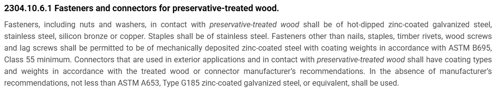
For use in preservative-treated wood, the IBC-2015 specifies fasteners that are hot-dipped galvanized, stainless steel, silicon bronze or copper. Section 2304.10.5.1 of IBC-2015 (Figure 1) covers fastener and connector requirements for preservative-treated wood (chemically treated wood). While chemically treated wood is part of the corrosion hazard, it is not the whole corrosion hazard. Weather exposure, airborne chemicals and other environmental conditions contribute to the corrosion hazard for metal hardware. In addition, the main issue with the code-referenced requirements for fasteners and connectors used with preservative-treated wood is that not all preservative treatments deliver the same corrosion hazard and not all fasteners can be hot-dip galvanized.

Figure 1: Section 2304.10.5.1 IBC-2015.

What if we want to use an alternative base material or coating for fasteners?

How do we evaluate the corrosion resistance of the alternative material or coating? The codes do not provide test methods to evaluate alternate materials and coatings. However, the International Code Council–Evaluation Service (ICC-ES) developed acceptance criteria to evaluate alternative coatings that are not code recognized for use in different environments. The purpose of acceptance criteria ICC-ES AC257, Acceptance Criteria for Corrosion-Resistant Fasteners and Evaluation of Corrosion Effects of Wood Treatment Chemicals, is twofold: (1) to establish requirements for evaluating the corrosion resistance of fasteners that are exposed to wood-treatment chemicals, weather and salt corrosion in coastal areas; and (2) to evaluate the corrosion effects of wood-treatment chemicals. In this blog post, we will concentrate on the evaluation of corrosion resistance of fasteners. The criteria provide a protocol to evaluate the corrosion resistance of fasteners where hot-dip galvanized fasteners serve as a performance benchmark. The fasteners evaluated by these criteria are nails or screws that are exposed directly to wood-treatment chemicals and that may be exposed to one or more corrosion accelerators like high humidity, elevated temperatures, high moisture or salt exposure.

The fasteners may be evaluated for any of the four exposure conditions:

  1. Exposure Condition 1 with high humidity. This test can be used to evaluate fasteners that could be exposed to high humidity. Typical applications that fall under this category are treated wood in dry-use applications.
  2. Exposure Condition 2 with untreated wood and salt water. This test can be used to evaluate fasteners that are above ground but exposed to coastal salt exposure.
  3. Exposure Condition 3 with chemically treated wood and moisture. This test covers all the general construction applications.
  4. Exposure Condition 4 with chemically treated wood and salt water. Typical applications include coastal construction applications.

Depending on the exposure condition being used for fastener evaluation, the fasteners are installed in wood that could be either chemically treated or untreated. Then the wood and the fasteners are placed in the chamber and artificially exposed to the evaluation environment. Two types of test procedures are to be completed for exposure condition 2 through 4. The purpose of these tests is not to predict the corrosion resistance of the coatings being evaluated, but to compare them to fasteners with the benchmark coating (ASTM A153, Class D) in side-by-side exposure to the accelerated corrosion environment.

ASTM B117 Continuous Salt-Spray Test

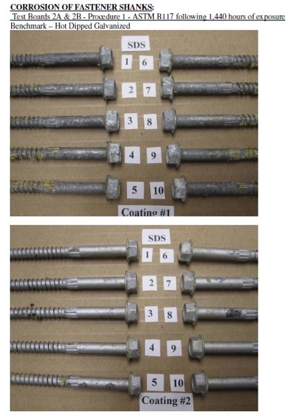
ASTM B117 is a continuous salt-spray test. For Exposure Condition 3, distilled water is used instead of salt water. The fasteners are continuously exposed to either moisture or salt spray in this test, and the test is run for about 1,440 hours after which the fasteners are evaluated for corrosion. This is an accelerated corrosion test that exposes the fasteners to a corrosive attack so the corrosion resistance of the coatings can be compared to a benchmark coating (hot-dip galvanized).

ASTM G85, Annex A5

The second test is ASTM G85, Annex A5 which is a cyclic test with alternate wet and dry cycles. The cycles are 1-hour dry-off and 1-hour fog alternatively. This is a cyclic accelerated corrosion test and relates more closely to real long-term exposure. This test is more representative of the actual environment than the continuous salt-spray test.  As in the ASTM B117 test, the fasteners along with the wood are exposed to 1,440 hours, after which the corrosion on the fasteners is evaluated and compared to fasteners with the benchmark coating.

Test Method and Evaluation

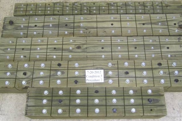
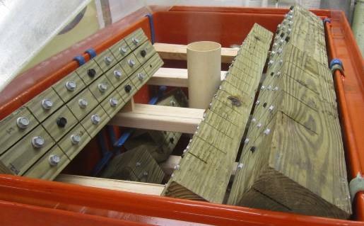
The test process involves installing 10 benchmark fasteners along with 10 fasteners for each alternative coating being evaluated. The fasteners are arranged in the wood with a spacing of 12 times the fastener diameter between the fasteners. A kerf cut is provided in the wood between the fasteners to isolate the fasteners as shown in Figure 2 and to ensure elevated moisture content in the wood surrounding the fastener shank. The moisture and retention levels of the wood are measured, and the fasteners are then installed in the chamber as shown in Figure 3 and exposed to the designated condition. The test is run for the period specified, after which the fasteners are removed, cleaned and compared to the benchmark for corrosion evaluation. Figure 4 shows the wood and fastener heads after 1,440 hours (60 days). The heads and shanks of the fasteners are visually graded for corrosion in accordance with ASTM D610. If the alternate coating performs equivalent to or better than the benchmark coating — that is, if the corrosion is no greater than in the benchmark — then the coating has passed the test and can be used as an alternative to the code-approved coating. Figure 5 shows the benchmark and alternative fasteners that are removed from the chamber after 1,440 hours.

As you can see, the alternative coatings have to go through extended and rigorous testing and evaluation as part of the approval process before being specified for any of the fasteners. Some alternative coatings provide even better corrosion resistance than the code recognized options. Sometimes, also, the thickness of these alternative coatings may be smaller than the thick coating required for hot-dip galvanized parts. Some of our coatings, such as the Double-Barrier coating, the Quik Guard® coating and the ASTM B695 Class 55 Mechanically Galvanized have gone through this rigorous testing and have been approved for use in preservative-treated wood in the AC257 Exposure Conditions 1 and 3. In addition, these coatings have been qualified for use with chemical retentions that are typical of AWPA Use Category 4A – General Ground Contact. No salt is found in AC257 Exposure Conditions 1 and 3. Please refer to our Fastener Systems Catalog, C-F-14, pages 13–15 for corrosion recommendations and pages 16–17 for additional information on coatings.

What do you look for specifically in a fastener? Do you have a preference for a certain coating type or color? Let us know in the comments below!

Figure 2: Fasteners with different coatings along with the benchmark, installed in wood and separated by kerf cuts.
Figure 3: Fasteners and wood pieces installed in the chamber.
Figure 4: Snap shot of fasteners in ASTM B117 chamber after 1,440 hours.
Figure 5: Fasteners after 1,440 hours of exposure, removed from the wood, cleaned and compared to benchmark. Coating 1 – Benchmark (Hot- dip Galvanized) and Coating 2 (Alternative coating).

Specifying Self-Drilling Screws: “Standard” vs. “Engineered”

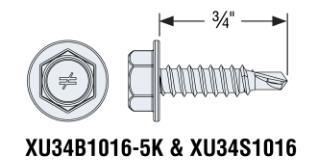
In my past life as a Design Engineer, when specifying a screw the size of the screw was the key feature that I considered. In my mind, a #10 screw performed better than #8, and a #12 was better than #10 and all #10 screws were the same. But that is not always true. Just as a shoe size or a dress size may not be exactly the same for all brands, a screw of the same size from different manufacturers may perform differently. The head type, head design, thread design (fine, coarse, thread angle, pitch), thread type (like box threads, buttress threads, unified, square) and drill point type (like #1, #3, #5 drill point) can influence the performance of a screw. When innovatively designed, a #10 engineered screw can meet or exceed the performance of a #12 or #14 screw in loads and drill time and could result in cost savings. You can use fewer screws, which would mean labor savings. For example, our newly designed XU34B1016 screw, which is a #10 screw with 16 threads per inch, a hex washer head and a #1 drill point, that performs better than a #14 standard screw in lighter gauge steels.

screws1

What Are Self-Drilling Tapping Screws?

Self-drilling tapping screws, or self-drilling screws, as the name implies, drill their own hole, eliminating the need for predrilling, and form or cut internal mating threads.  They are  relatively fast to  instal compared to bolts or welds. Unlike pins, they do not require a thick support material to be used. They can be used in very thin steel, such as 26 gauge, up to steel that is ½” thick. Self-drilling screws may be a perfect choice for most applications involving cold-formed steel (CFS). They are most commonly used for CFS connections: either attaching CFS to CFS, wood to CFS or CFS to wood. They are a logical choice when the other side of the connection or material is not accessible.

Most self-drilling screws are made of steel wire that meets the specification of ASTM A510 minimum grade 1018 material as specified in ASTM C1513 standard. Self-drilling screws are heat treated  to case harden then so that they meet the hardness, ductility, torsional strength and drill drive requirements as specified in ASTM C1513 standard.  ASTM C1513 refers to SAE J78 for the dimensional and performance requirements of self-drilling screws.

Screw Selection

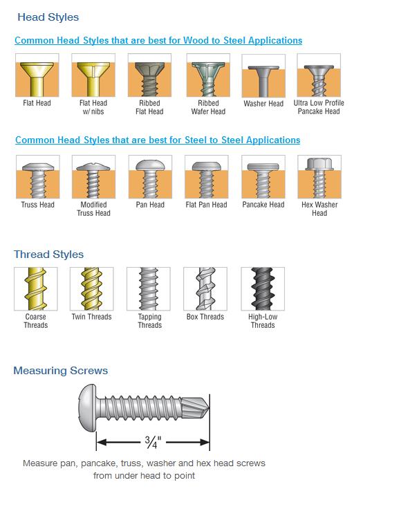
While selecting the screw, you need to figure out the head type that works for the application. For example, a flat-head screw would be a good choice for wood-to-steel applications, but for steel-to-steel applications, a hex head or a pan head may be a better choice. Similarly, the length of the screw should be sufficient to fasten  the members of the connection together. According to Section D1.3 of AISI S200, the screw should be at least equal in length to the total thickness of the material including gaps with a minimum of three exposed threads. The length of the drill point is another important feature to consider. It should be long enough to drill through the entire thickness of the material before engaging the threads. This is because thread forming occurs with fewer revolutions than  the drilling process.   if the drill point length is not long enough, the screw threads can engage the connection material and the screw can bind and break.

screws2

Some drill points also have “wings” to  drill a hole in the material that is larger in diameter than the threaded shank. Screws with this kind of point are mainly used for wood-to-steel applications. The blog post by Jeff Ellis titled “Wings or No Wings” provides some useful insights for screws with wings when used in shearwall applications.

The Test Standards and Evaluation Criteria for Standard and Engineered Screws

Per Section D1 of AISI S200, screws used for steel-to-steel connections or sheathing-to-steel connections shall be in compliance with ASTM C1513 or an approved design or design standard.

For ASTM C1513–compliant screws (per AISI S100), Section E4 provides equations to calculate shear, pullout and pullover of screws used in steel-to-steel connections. It also provides safety and resistance factors for calculating allowable strength or design strength. These equations are based on the results of tests done worldwide and the many different types of screws used in the tests. As a result, these equations seem to have a great degree of conservatism.

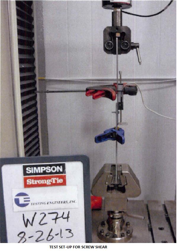
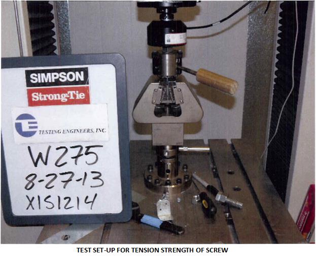
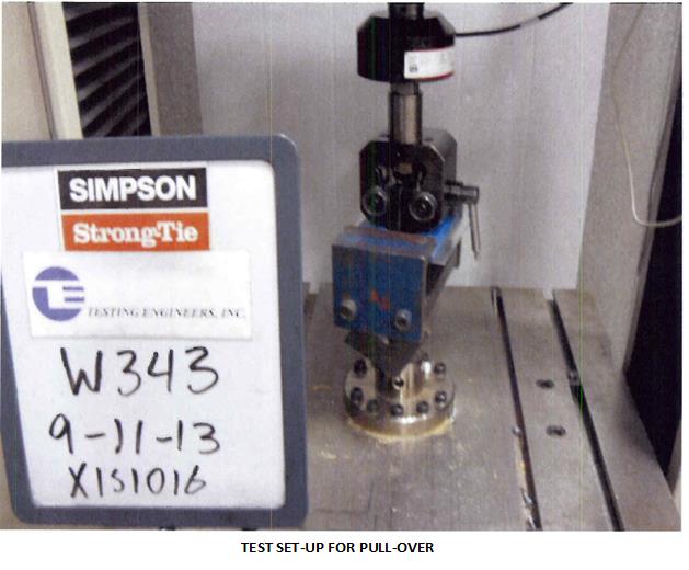
As discussed earlier, many factors, such as the head type and washer diameter, thread profile, drill point type and length, installation torque and the installation method affect or influence the performance of a screw. In order to qualify the screws as ASTM C1513–compliant or better performing, manufacturers need to have their screws evaluated per Acceptance criteria for Tapping Screw Fasteners AC118 developed by International Code Council – Evaluation Service. The criteria have different requirements depending on whether the intention is to qualify as standard screws or proprietary screws.  For proprietary screws, connection shear, pullout and pullover tests are performed in accordance with the AISI S905 test method. The shear strength and tensile strength of the screw itself are evaluated per test standard AISI S904. The safety and resistance factors are calculated in accordance with Section F of AISI S100. The pictures below are some test set-ups per AISI S905 and AISI S904 test procedures.

screws3 screws4 screws5

Another important consideration is corrosion resistance. AC118 has a requirement for testing the fasteners for corrosion resistance in accordance with ASTM B117 for a minimum of 12 hours. The screws tested shall not show any white rust after 3 hours or any red rust after 12 hours of the test. At the same time, it is important to keep in mind  that  hardened screws are prone to hydrogen embrittlement and are not recommended for exterior or wet condition applications. Also, these screws are  not recommended for use with dissimilar metals.  If self-drilling screws are to be used in exterior environments, the screws need to be selectively heat treated to keep the core and surface hardness in a range that  reduces the susceptibility to hydrogen embrittlement. Other fastener options for exterior environments are stainless-steel screws.

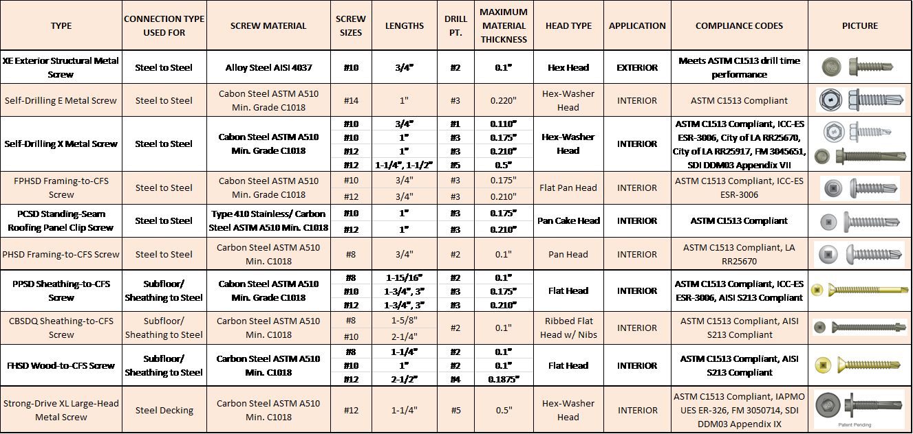
This table shows are some of our screw offerings for CFS applications. Our stainless-screw options can be found in  Fastening Systems Catalog (C-F-14) or at www.strongtie.com.

screw6a

What are the screws that you most commonly specify? Share your screw preferences and your ideas on self-drilling screws in your comments below.

Designing Built-Up Columns

Designing built-up columns? Now there’s a way to mechanically laminate multiple 2x members to meet the specifications in the National Design Specifications for wood. Simpson Strong-Tie evaluated Strong-Drive® SDW Truss-Ply screws for attaching multiple laminations with easier installation methods. With these screws, there’s no longer a need to nail from both sides of the column, or to use not-so-common 30d nails as specified in the NDS, or to pre-drill for bolts. Instead, installers can now install all the screws from one side of the built-up column, which provides time and cost savings.

Continue Reading

Design Examples for Steel Deck Diaphragm Calculator Web App

This week’s blog post was written by Neelima Tapata, R&D Engineer for Fastening Systems. She works in the development, testing and code approval of fasteners. She joined Simpson Strong-Tie in 2011, bringing 10 years of design experience in multi- and single-family residential structures in cold-formed steel and wood, curtain wall framing design, steel structures and concrete design. Neelima earned her bachelor’s degree in Civil Engineering from J.N.T.U in India and M.S. in Civil Engineering with a focus on Structural Engineering from Lamar University. She is a registered Professional Engineer in the State of California.

Like most engineers, you are probably often working against tight deadlines,  on multiple projects and within short delivery times. If you have ever wished for a design tool that would make your work easier, we have an app for that. It’s a simple, quick and easy-to-use tool called the “Steel Deck Diaphragm Calculator” for designing steel deck diaphragms. This tool is so user friendly you can start using it in minutes without spending hours in training. This app can be found on our website, and you don’t need to install anything.

The Steel Deck Diaphragm Calculator has two parts to it: “Optimized Solutions” and “Diaphragm Capacity Tables.” Optimized Solutions is a Designer’s tool and it offers optimized design solutions based on cost and labor for a given shear and uplift. The app provides multiple solutions starting with the lowest cost option using different Simpson Strong-Tie® structural and side-lap fasteners. Calculations can be generated for any of the solutions and a submittal package can be created with the code reports, Factory Mutual Approval reports, fastener information, corrosion information, available fliers, and SDI DDM03 Appendix VII and Appendix IX that includes Simpson Strong-Tie fasteners. Currently, this tool can be used for designing with only Simpson Strong-Tie fasteners. We will be including weld options in this calculator very soon. Stay tuned!

The Diaphragm Capacity Tables calculator can be used to develop a table of diaphragm capacities based on the effects of combined shear and tension.

steeldeck1

When “Optimized Solutions” is selected, the following input is requested:

Step 1: Building Information   ̶   Enter general information about the project, like the project name, the length and width of the building to be designed along with spacing between the support members such as joist spacing, is entered.

Step 2: Steel Deck Information   ̶   Select the type of the steel deck along with the fill type. You can select the panel width from the options or select “Any panel width” option for the program to design the panel width. Choose the deck thickness or select the “Optimize” option for the program to design the optimum deck thickness. You also have an option of editing the steel deck properties to accommodate proprietary decks that are within the limitations of SDI DDM03 Section 1.2. Select the joist steel (support) thickness that the deck material will be attached to. For some fasteners, the shear strength of the fastener is dependent on this support thickness.

Step 3: Load Information   ̶  Enter the shear and uplift demand and select the load type as either “wind” or “seismic” and the design method as “ASD” or “LRFD.”

Step 4: Fastener Information   ̶  This is the last step of input before designing. In the fastener information section, you have the option to choose a structural and side-lap fastener or let the program design the most cost-effective structural and side-lap options. This can be done by checking the “Provide optimized solutions” option. The default options in the program are usually the best choice. However, you can change or modify as needed for your project. You can also set the side-lap fastener range or leave it to the default of 0 to 12 fasteners.

Now let’s work on an example:

Design a roof deck for a length of L = 500 ft. and a width b = 300 ft. The roof deck is a WR (wide rib) type panel, with a panel width of 36″.  The roof deck is supported by joists that are ¼” thick and spaced at 5 ft. on center. Design the diaphragm for wind loading using Allowable Stress Design method. The diaphragm should be designed for a diaphragm shear of 1200 plf. and a net uplift of 30 psf. The steel deck is ASTM A653 SS Grade 33 deck with Fu = 45 ksi.

This information is entered in the web app, as seen below.

steeldeck2

After inputting all the information, click on the Calculate button. You will see the five best solutions sorted by lowest cost and least amount of labor. Then click on the Submittal Generator button. Upon pressing this button, a new column called “Solution” is added with an option button for each solution. You can select any of the solutions. Below the Submittal Generator button, you can select various Code Reports and Approvals and Notes and Information selections that you want included in the submittal. After selecting these items, click on the Generate Submittal button. Now a pdf package will be generated with all of your selections.

steeldeck3

Below is the screen shot of the first page containing Table of Contents from the PDF copy generated. The PDF copy contains the solutions generated by the program, then the detailed calculations for the solution that is selected. In this case, as you can see in the screen shot above, detailed calculations for solution #1 are included with XLQ114T1224 structural screws; XU34S1016 side-lap screws; 36/9 structural pattern and with (10) side-lap fasteners; diaphragm shear strength of 1205 plf. and diaphragm shear stiffness of 91.786 kip/in. The detailed calculations are followed by IAPMO UES ER-326 code report and FM Approval report #3050714.

steeldeck4

Below is another example of a roof deck to be designed for multiple zones.

Design a roof diaphragm that will be zoned into three different areas. Zoning is a good way to optimize the economy of the roof diaphragm. Below are the required diaphragm shears and uplift in the three zones.

Zone 1: Diaphragm shear = 1200 plf.; Net uplift = 30 psf.; Length and width of zone 1 = 300 ft. x 200 ft.
              Joist spacing = 5 ft.

Zone 2: Diaphragm shear = 1400 plf.; Net uplift = 0 psf.; Length and width of zone 2 = 500 ft. x 200 ft.
              Joist spacing = 5.5 ft.

Zone 3: Diaphragm shear = 1000 plf.; Net uplift = 25 psf.; Length and width of zone 3 = 300 ft. x 200 ft.
              Joist spacing = 4.75 ft.

Refer to the example above for all other information not given.

To design for multiple zones first select the Multi-Zone Input button, which is below the Fastener Information section as shown below:

steeldeck5

When you click on the Multi-Zone Input button, you can see a toggle button appearing above a few selections as shown below. The default for the toggle button is globalbutton, which means that this selection is same for all the zones. You can click on the toggle button to change to zonebutton. Then the selection below changes to a label and reads Zone Variable. After all the selections that need to be zone variables are selected, click the Add Zone button. Keep adding zones as needed. A maximum of five zones can be added. After creating the zones, add the information for each zone and click the Calculate button.

steeldeck6

When the Calculate button is clicked, the results for each zone are listed. The five best solutions are listed for each of the zones as shown below.

steeldeck7

Similar to previous example, select the Generate Submittal button to select the solutions to be included in the submittal generator. Select one solution for each zone and then check the items like the code reports or notes to be included in the submittal. Click Generate Submittal to create the submittal package.

See the screen shot below for the steps.

steeldeck8

Now that you know how easy it is to design using our web app, use this app for your future projects. We welcome your feedback on features you find useful as well as your input on how we could make this program more useful to suit your needs. Let us know in the comments below.