We often get questions about using fasteners different from those listed in a connector’s catalog load tables. A question came up recently, and I said, “I did a blog post about that not too long ago.” Turns out that blog post is over 10 years old, which no longer qualifies as “not too long ago.” The options we offer as alternative fasteners for our connectors have grown since that blog post, so I thought it was worth revisiting the topic.
Tag: fasteners
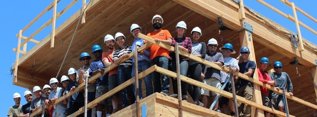
From Research to Real-World Application: Pioneering Mass Timber Innovation
Brian DeMeza’s journey from pursuing his Master of Science degree at Oregon State University (OSU) to his current role as a Senior Field Engineer at Simpson Strong-Tie has brought him full circle with his recent involvement in the six-story NHERI TallWood project. His hands-on experience in this project played a pivotal role in shaping his passion and focus on mass timber as a potential career path.
Common Technical Engineering Inquiries – Part III: Fasteners
This is the last of a three-part series covering common questions we receive in our engineering department. Part 1 consisted of frequently asked questions related to our anchor products (view Part 1 here), while part 2 covered connector products (view Part 2 here). These are questions that come directly into our call center, along with questions submitted through the website, our engineering email queues, and our sales team.
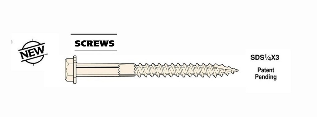
Ninth Day of Trivia — Strong-Drive® SDS Screws
It’s difficult to talk about connectors without talking about fasteners. Simpson Strong-Tie developed the Strong-Drive® SDS Heavy-Duty Connector screw as a high-capacity alternative to nails or bolts, and the first connector using them was the PHD Predeflected Holdown. We released in both the PHD and the SDS screw in 1997.
Why Fire-Rated Hangers Are Required in Type III Wood-Frame Buildings
One of the first mixed-use designs I worked on as a consulting structural engineer was a four-story wood-frame building over two levels of parking. Designing the main lateral-force-resisting system with plywood shearwalls was a challenge for this project that required new details to meet the high design loads. The high overturning forces were resisted using the Simpson Strong-Tie® Strong-Rod™ anchor tiedown system, which incorporates high-strength rods, bearing plates and shrinkage compensation devices.

Simpson Strong-Tie in Latin America: Our 2022 Chile Seminar
Our Director of International Sales in Latin America, Cyndi Chandler, organized our annual sales seminar in Chile. This was a great opportunity to connect with our engineers and specifiers in Latin America and educate them about the various products and resources we offer. Learn more about this dynamic two-day seminar and the products we demonstrated in Chile.

My Experience as an Engineering Intern from Gallatin, Tennessee
This summer we welcomed engineering student Sam Lewis to intern at our Gallatin, Tennessee branch. He discusses his hands-on opportunity to test our fasteners, learn more about our company culture and people.

New Materials Require New Hardware — Three Fasteners Engineered Specifically for Mass Timber Construction
Simpson Strong-Tie has always been a leader in designing innovative products for various construction markets. As an R&D engineer, I enjoy the opportunities for continuous exploring, experimenting and learning that come with my role. There’s never a dull moment working in research and development! At present, I’m thrilled to be part of a team that works on developing products for construction using cross-laminated-timber (CLT) and other forms of mass timber. So I have the honor of introducing three amazing fastener products that are load rated for use in CLT, wood, glulam and structural composite lumber (SCL) products (e.g., LVL, PSL, LSL).
SDWS Timber Screw – The Evolution Continues
Simpson Strong-Tie® R&D engineers are always looking to make products even better and more cost effective, in ways that will improve life not only for homeowners, but also for Designers and builders. In the following post, Aram Khachadourian explains how the newly designed SawTooth™ point on our code-listed Strong-Drive® SDWS Timber screw makes driving faster and easier with no predrilling. The flat head also makes connector and sheathing placement a lot smoother.
Continue Reading

Revisiting Spanning the Gap

Three years ago, we created this blog post based on a technical support question we often receive about allowable fastener loads for ledgers to wood framing over gypsum board. Given that this is still a frequent question and a relevant topic, we decided to revisit the post and update it.
Drywall. Wall board. Sheetrock. Sackett Board? A product called Sackett Board was invented in the 1890s, which was made by plastering within wool felt paper. United States Gypsum Corporation refined Sackett Board for several years until 1916, when they developed a new method of producing boards with a single layer of plaster and paper. This innovation was eventually branded SHEETROCK®. More details about the history of USG can be found here.
No matter what you call it, gypsum board is found in almost every type of construction. Architects use it for sound and fire ratings, while structural engineers need to account for its weight in our load calculations. A common technical support question we receive is for allowable fastener loads for ledgers to wood framing over gypsum board.
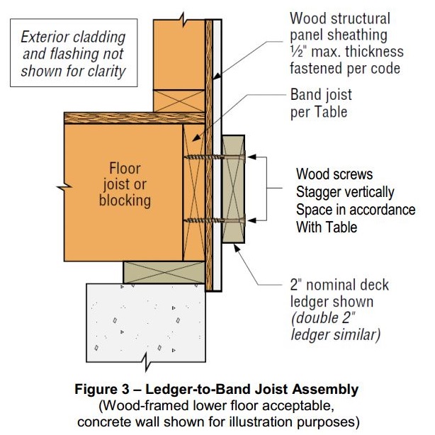
One method to evaluate a fastener spanning across gypsum board is to treat the gypsum material as an air gap. Technical Report 12, General Dowel Equations for Calculating Lateral Connection Values, is published by the American Wood Council.

TR12 has yield limit equations that allow a designer to account for a gap between the main member and side member of a connection. With a gap of zero (g=0), the TR12 equations provide the same results as the NDS yield limit equations.
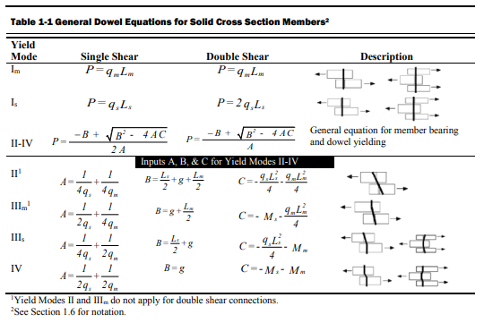
The equations are fairly complex, but it should be intuitive that the calculated fastener capacity decreases with increasing gap. Engineers are often surprised to see a 40, 50, even 60% drop in fastener capacity with one layer of 5/8” gypsum board. So what else can you do?
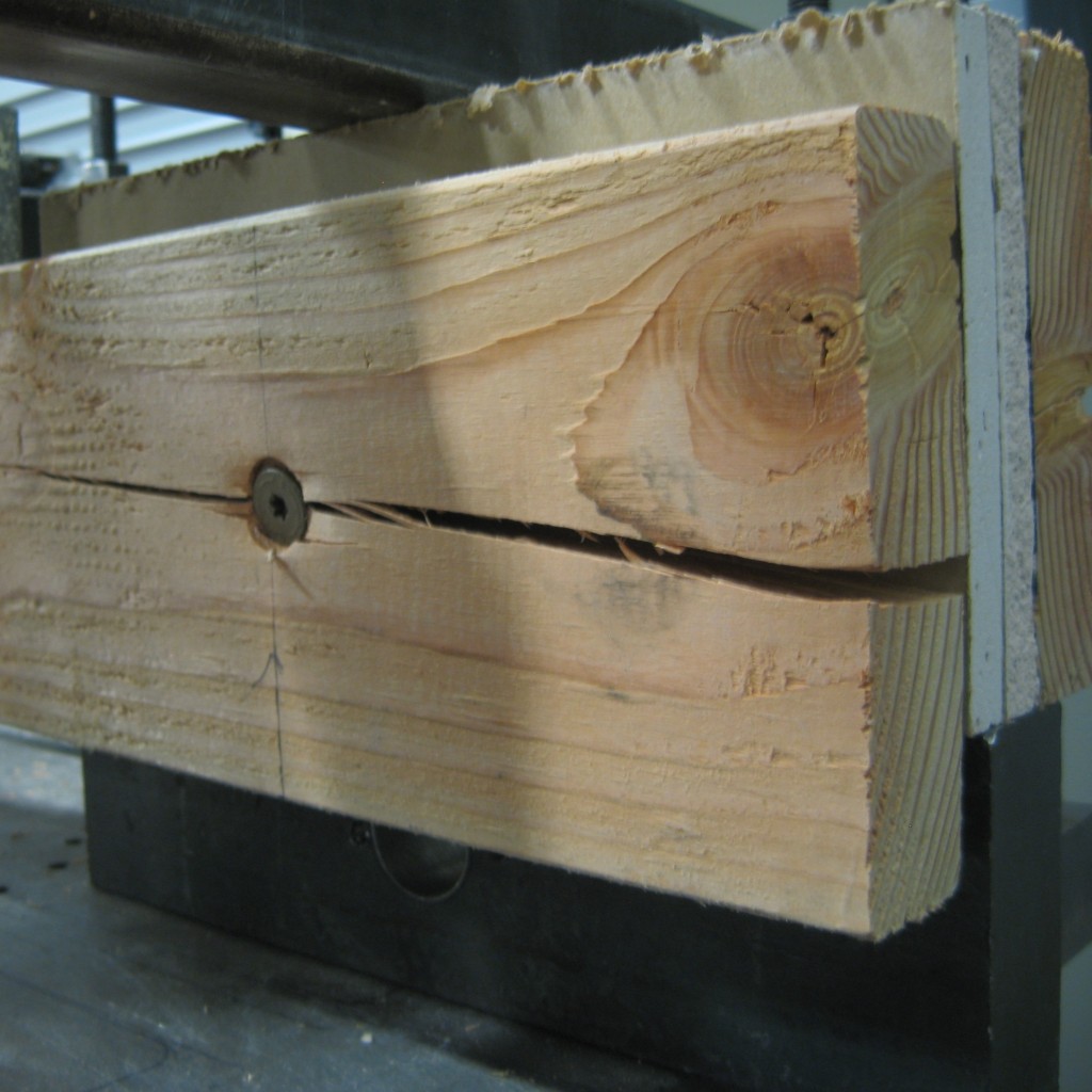
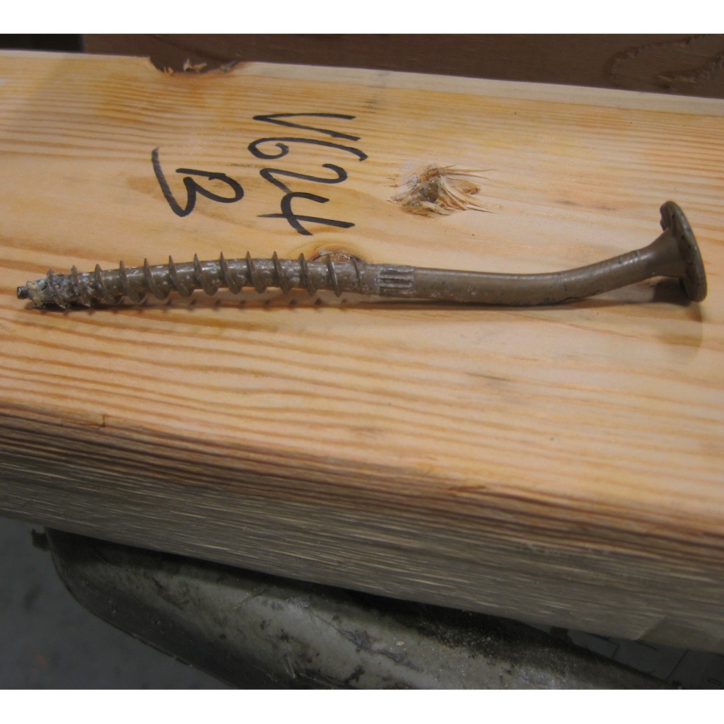
Testing, of course! In So, What’s Behind a Screw’s Allowable Load? I discussed the methods used to load rate a proprietary fastener such as the Simpson Strong-Tie® Strong-Drive® SDS or SDW screws. To recap, ICC-ES Acceptance Criteria for Alternate Dowel Type Fasteners, AC233, allows you to calculate and do verification tests, or load rate based on testing alone. We develop our allowable loads primarily by testing, as the performance enhancing features and material optimizations in our fasteners are not addressed by NDS equations.
So to determine the performance of a fastener installed through gypsum board, we tested the fastener through gypsum board. This is easier to do if you happen to have a test lab with a lot of wood and fasteners in it. We did have to run down to the local hardware store to pick up gypsum board for the testing.
A full set of allowable loads for Strong-Drive SDWH and SDWS are available on strongtie.com. The information is given as single fastener shear values for engineered design, and also screw spacing tables for common ledger configurations. As much fun as writing spreadsheets to do the Technical Report 12 calculations is, having tabulated values based on testing is much easier.
Fastening Systems
In the fastener marketplace, Simpson Strong-Tie stands apart from the rest. Quality and reliability is our top priority.