So, What’s Behind A Structural Connector’s Allowable Load? (Holdown Edition)

This is Part 1A of a four-part series I’ll be doing on how connectors, fasteners, anchors and cold-formed steel systems are load rated.

I envisioned doing a four-part series on how connectors, fasteners, anchors, and cold-formed steel are load rated. After writing the first installment on connectors, I realized that connectors are a bit more complicated, since the testing and evaluation for joist hangers (or similar devices) is different than testing for holdown devices. And I wanted to discuss holdowns. So without belaboring the apology for my numbering system, this will be part 1A of the series – still discussing wood connectors, but focusing on holdowns and some of the unique requirements in their load rating.Continue Reading

So, What's Behind A Structural Connector's Allowable Load? (Holdown Edition)

This is Part 1A of a four-part series I’ll be doing on how connectors, fasteners, anchors and cold-formed steel systems are load rated.
I envisioned doing a four-part series on how connectors, fasteners, anchors, and cold-formed steel are load rated. After writing the first installment on connectors, I realized that connectors are a bit more complicated, since the testing and evaluation for joist hangers (or similar devices) is different than testing for holdown devices. And I wanted to discuss holdowns. So without belaboring the apology for my numbering system, this will be part 1A of the series – still discussing wood connectors, but focusing on holdowns and some of the unique requirements in their load rating.
 AC155, Acceptance Criteria for Hold-Downs (Tie-Downs) Attached to Wood Members, was first developed in 2005 to better address boundary conditions, deflection limits, and wood post limits. Prior to AC155, holdowns were evaluated based on testing on a steel jig with a safety factor of 3.0 and an NDS bolt calculation. Deflection at the allowable load was simply reported so that it was available for use in design, but there was not a deflection limit that affected the load rating.

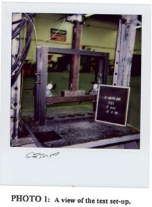
Bolted Holdown – Steel Jig Test

 In the steel jig setup shown, the jig keeps the holdowns stationary while the rectangular bar underneath the holdowns is pushed downward to simulate an uplift force. This was (and still is) an effective method of testing the capacity of the steel body of a holdown, but it does not tell you a lot about the deflection of the holdown when installed on a wood member. Since story-drift is such a critical component to shearwall performance and the deflection of holdowns has a significant effect on the total drift, this needed to be address in the holdown test standard.
Continue Reading

Out-of-Plane Wall Anchorage Design

While the Simpson Strong-Tie Tye Gilb R&D lab in Stockton is a large testing facility, the world’s largest R&D lab is Mother Nature herself. Natural disasters such as earthquakes or storms put our engineering designs to the test. In this week’s blog post, I’ll be turning attention to wall anchorage for out-of-plane forces and the lessons we have learned from Mother Nature so far.

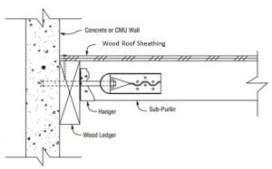
The 1979 building code incorporated many of the lessons learned from the 1971 San Fernando earthquake. In 1994, Mother Nature put the 1979 building code to the test with the January 17 Northridge earthquake. The Northridge earthquake showed that some of the increased design and detailing requirements in the 1979 building code worked well to improve performance over what was observed in 1971. However, it also revealed to researchers that acceleration at the roof level of single story warehouse buildings were three to four times the ground acceleration. The combination of higher than expected acceleration and excessive deformation of the wall anchorage assembly caused many wall anchorage failures.

Figure 1 Out-of-Plane Wall Anchorage Assembly

Several changes in the design forces used for wall anchorage and additional detailing requirements were incorporated in the 1997 Uniform Building Code. The requirements have been refined with each new building code, but overall the requirements and design forces have remained about the same under the current International Building Code. Wall anchorage design is governed by ASCE 7-05 and ASCE 7-10 Section 12.11. These provisions aim to mitigate the brittle wall anchorage failures observed in past earthquakes by increasing the design force and in Seismic Design Categories C through F, requiring:Continue Reading

Who’s Thinking About Deck Safety? I Am!

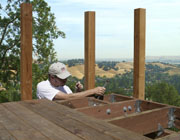
A few months ago, the Today Show asked Simpson Strong-Tie to demonstrate a deck collapse to educate the public about deck safety. Often through the Fall and Winter months, decks go unused yet see a lot of activity from rain, sleet and snow. When the sun comes out in the Spring, people get out on their decks again without much thought about how the elements may have affected the important connections on their deck.

In addition to the weather, there are other factors to consider about deck safety:

  • Experts agree that the average life expectancy of a wood deck is 10 to 15 years.
  • It’s estimated that there are millions of decks in the U.S. that are beyond their useful life and may be unsafe.
  • The number of deck collapses has increased in recent years.
  • Within the past five years, 651 injuries and four deaths have occurred due to deck collapse.

So, I’m thinking about deck safety. I thought I’d share with you the “5 Warning Signs of an Unsafe Deck” we discussed on the Today Show:

Continue Reading

Who's Thinking About Deck Safety? I Am!

A few months ago, the Today Show asked Simpson Strong-Tie to demonstrate a deck collapse to educate the public about deck safety. Often through the Fall and Winter months, decks go unused yet see a lot of activity from rain, sleet and snow. When the sun comes out in the Spring, people get out on their decks again without much thought about how the elements may have affected the important connections on their deck.
In addition to the weather, there are other factors to consider about deck safety:

  • Experts agree that the average life expectancy of a wood deck is 10 to 15 years.
  • It’s estimated that there are millions of decks in the U.S. that are beyond their useful life and may be unsafe.
  • The number of deck collapses has increased in recent years.
  • Within the past five years, 651 injuries and four deaths have occurred due to deck collapse.

So, I’m thinking about deck safety. I thought I’d share with you the “5 Warning Signs of an Unsafe Deck” we discussed on the Today Show:
Continue Reading

So, What’s Behind A Structural Connector’s Allowable Load?

This is Part 1 of a four-part series I’ll be doing on how connectors, fasteners, anchors and cold-formed steel systems are load rated.

Today I did my presentation for the WoodWorks webinar on Testing and Product Evaluation of Products for Wood-framed Construction. We covered a lot of material regarding code requirements for using alternate materials or construction methods, how testing and evaluation criteria are developed, and some specifics on several Acceptance Criteria (AC’s) that are commonly used for connector evaluations. We also discussed some specific testing requirements, so I thought it would be timely to discuss some of those issues in this week’s blog post.

So, how are structural connectors for light frame wood construction load rated? What’s behind the allowable loads information published in Simpson Strong-Tie literature or wood connector evaluation reports? These are things that you might find yourself wondering while driving to the office or jobsite, or on a Sunday afternoon while enjoying your favorite iced tea or barley-based beverage.

The short answer is: testing, calculations, and of course, sound engineering judgment.

Continue Reading

So, What's Behind A Structural Connector's Allowable Load?

This is Part 1 of a four-part series I’ll be doing on how connectors, fasteners, anchors and cold-formed steel systems are load rated.
Today I did my presentation for the WoodWorks webinar on Testing and Product Evaluation of Products for Wood-framed Construction. We covered a lot of material regarding code requirements for using alternate materials or construction methods, how testing and evaluation criteria are developed, and some specifics on several Acceptance Criteria (AC’s) that are commonly used for connector evaluations. We also discussed some specific testing requirements, so I thought it would be timely to discuss some of those issues in this week’s blog post.
So, how are structural connectors for light frame wood construction load rated? What’s behind the allowable loads information published in Simpson Strong-Tie literature or wood connector evaluation reports? These are things that you might find yourself wondering while driving to the office or jobsite, or on a Sunday afternoon while enjoying your favorite iced tea or barley-based beverage.
The short answer is: testing, calculations, and of course, sound engineering judgment.
Continue Reading

Why a Structural Boundary Member Between a Truss/Rafter is Not Optional

Blocking or boundary member?

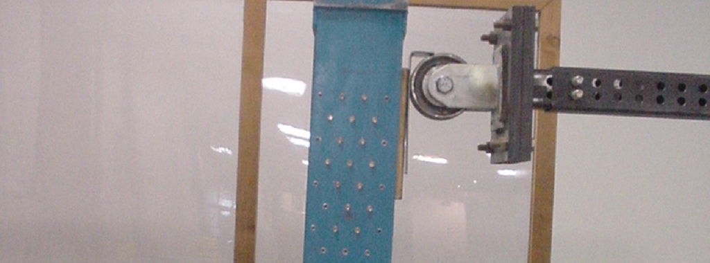
In my experience traveling across the country observing wood-framed construction, it was apparent that east of the Rocky Mountains, structural wood members in-line with supporting walls between roof framing cease to be installed. Some may call these wood members blocking and deem them as optional. And often in a humid environment, installation of these members may be ardently resisted in order to provide ample attic ventilation and prevent mold growth. It is important, however, to understand that this blocking creates the structural boundary members for the roof diaphragm and it is not optional.

Continue Reading

How Do You Use Technology To Make Your Job Easier?

I confess to being a bit of a technology junkie. I think it was around 1995 when I first overcame my fears and cracked open my computer case, installed a new hard drive and upgraded to an enormous 8 megabytes of RAM. While I still enjoy building my own home computer every now and then, it seems like keeping up with technology is a full-time job. For every new website or app, you can expect two or three more just like it to follow. Trying to filter through all of that information to find what’s useful to your specific job, process or project can be impossible.

I’ve found it’s usually best to let the need dictate the technology, versus the other way around. When I was designing buildings, contractor sketches or descriptions of field issues were often not clear (especially the ones that had been faxed 5 times!). Sometimes we could figure it out with several phone calls, but other situations would require a field visit. A photograph would work, but developing film and sending the photos would take too long. The development of inexpensive digital cameras so field questions could be e-mailed with photos really streamlined my process for responding to field issues.

Continue Reading