

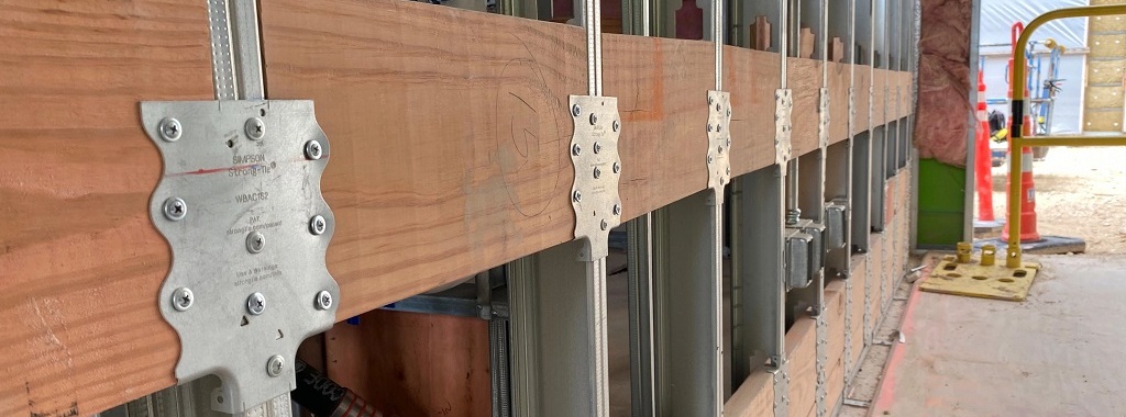
Engineers spend much of their career designing and detailing main structural members which are exposed to significant structural loads. An experienced engineer will often master this type of design and excel at detailing an efficient building system. However, these same savvy engineers are sometimes left scratching their heads when tasked with providing a clean and simple design for attaching components such as cabinets, shelves or handrails to interior finish. Simpson Strong-Tie’s versatile new WBAC Wood Backing Steel Connector provides the engineer with a fully tested design solution that efficiently and easily attaches wood backing members for heavy wall hangings.
Category: Cold-Form Steel Connectors
With more than 50 years of experience in product design, testing and manufacturing, Simpson Strong-Tie provides comprehensive structural solutions for cold-formed steel construction.
Beat Building Drift with the New DSSCB Drift Strut Slide Connector from Simpson Strong-Tie
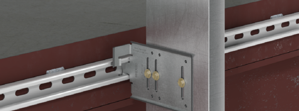
Structural engineers concerned with building envelopes are always looking for better solutions that help isolate the cladding from the primary structure in conditions where large building drift is a concern. Simpson Strong-Tie has an answer with a unique and innovative solution, the new DSSCB (drift strut sliding clip bypass).
Continue Reading

The Top 5 Helpful Tips for Using CFS Designer™ to Optimize Your Workflows
Back in April of last year, I had the opportunity to show how our new CFS Designer software could help structural engineers “go lean” in their design process by eliminating repetitive tasks (while still meeting required design standards, of course!). Since then, I’ve had the opportunity to visit with hundreds of engineers in person to teach them about CFS Designer and how it can help them improve and optimize their workflows. As a power user of the software, I want to share my top tips for letting CFS Designer help you save the maximum amount of time.
Continue Reading
Decrypting Cold-Formed Steel Connection Design
As published in STRUCTURE magazine, September 2016. Written by Randy Daudet, P.E., S.E., Product Manager at Simpson Strong-Tie. Re-posted with permission.
One of the world’s greatest unsolved mysteries of our time lies in a courtyard outside of the Central Intelligence Agency (CIA) headquarters in Langley, Virginia. It’s a sculpture called Kryptos, and although it’s been partially solved, it contains an inscription that has puzzled the most renowned cryptanalysts since being erected in 1990. Meanwhile, in another part of the DC Beltway about 15 miles to the southeast, another great mystery is being deciphered at the American and Iron Institute (AISI) headquarters.Continue Reading

Get There Quicker! How CFS Designer Can Help Speed Up Your Design Process
Did you know that Simpson Strong-Tie is celebrating its 60th birthday this year? We started out with one punch press and the ability to bend light-gauge steel. Then, one Sunday evening in the summer of 1956, Barclay Simpson’s doorbell rang and a request for our first joist hanger led us into the wood connector business. Since then, we’ve continued to grow that business by focusing on our engineering, research and development efforts. Some might say that nowadays we’re an engineering company that also happens to manufacture products, as evidenced by our focus on developing technology tools over the past few years such as web calculators, an updated website and design software. Our focus on technology, however, is really another aspect of our continued commitment to excellence in manufacturing and our application of the tenets of lean manufacturing.
Many of you may already be familiar with the idea of lean manufacturing made famous by Toyota in the early 2000s, along with the principles of continual improvement and respect for people. The concept of continual improvement is based on the idea that you can always make small changes to improve your processes and products. Although they were established in a manufacturing setting, these ideals ring very true for engineering as well; eliminate steps in your design process that don’t add any value to the final project and always be on the lookout for tools or techniques that can speed up your process. Thinking lean isn’t about cutting corners to get your result faster, it’s about mindfully getting rid of the steps that aren’t helping you and finding better ways of doing everyday tasks.
As structural engineers, we can find ourselves working on a variety of projects that lead us to perform repetitive calculations to check different conditions, such as varying parapet heights on the exterior of a building, or we may find ourselves working with an unfamiliar material, such as light-gauge or cold-formed steel (CFS), where we have to take some time away from design to review reference materials such as AISI S200-12 North American Standard for Cold-Formed Steel Framing. Wouldn’t it be great if there were a design tool that could help you complete your light-gauge projects more quickly, in complete compliance with current building codes?
It turns out that Simpson Strong-Tie offers a design tool called CFS Designer™ to help structural engineers improve their project design flow. This program gives engineers the ability to design light-gauge stud and track members with complex beam loading and span conditions according to building code specifications. What does that actually mean, though? Allow me to illustrate with an example of a design project.
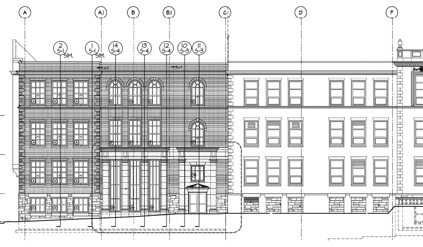
Let’s say you’re designing a building and part of your scope is the exterior wall framing, or “skin” of the building. You probably get sent some architectural plans that look something like this:
The architectural elevations will have wall section marks indicated for different framing situations. Two sample wall sections are shown in Figure 2.
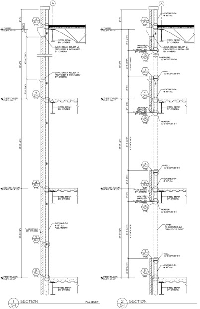
This building has several different wall section types that include door and window locations, varying parapet heights, diverse finish materials that need to meet different deflection criteria, and different connection points back to the base building. The traditional design calculation that you would need to run for one wall section might begin with a loading diagram similar to Figure 3 below.
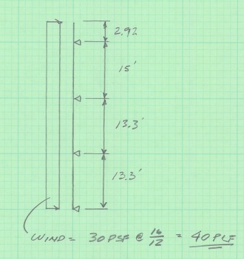
Once you have your loading diagram generated, you would need to use reference load tables or a computer analysis program to solve for the axial and moment demands, the reactions at the pinned supports, and the member deflections.
After you determine the demand loads, you would then need to select a CFS member with sufficient properties, and you may need to iterate a few times to find a solution that meets the load and deflection parameters. After you’ve selected a member with the right width, gauge and steel strength, you’ll need to select an angle clip that can handle the demand loads, as well as fasteners to connect the clip to the CFS stud and to the base building. You would also need to also check the member design to ensure that it complies with bridging or bracing requirements per AISI. Then, after all that, you’d have to repeat the process again for all of the wall section types for your project.
Just writing out that whole process took some time, and you can imagine that actually running the calculations takes quite a bit longer. I think we can all agree that the design process we’ve outlined is time-consuming, and here’s where using CFS Designer™ to streamline your design process can really help.
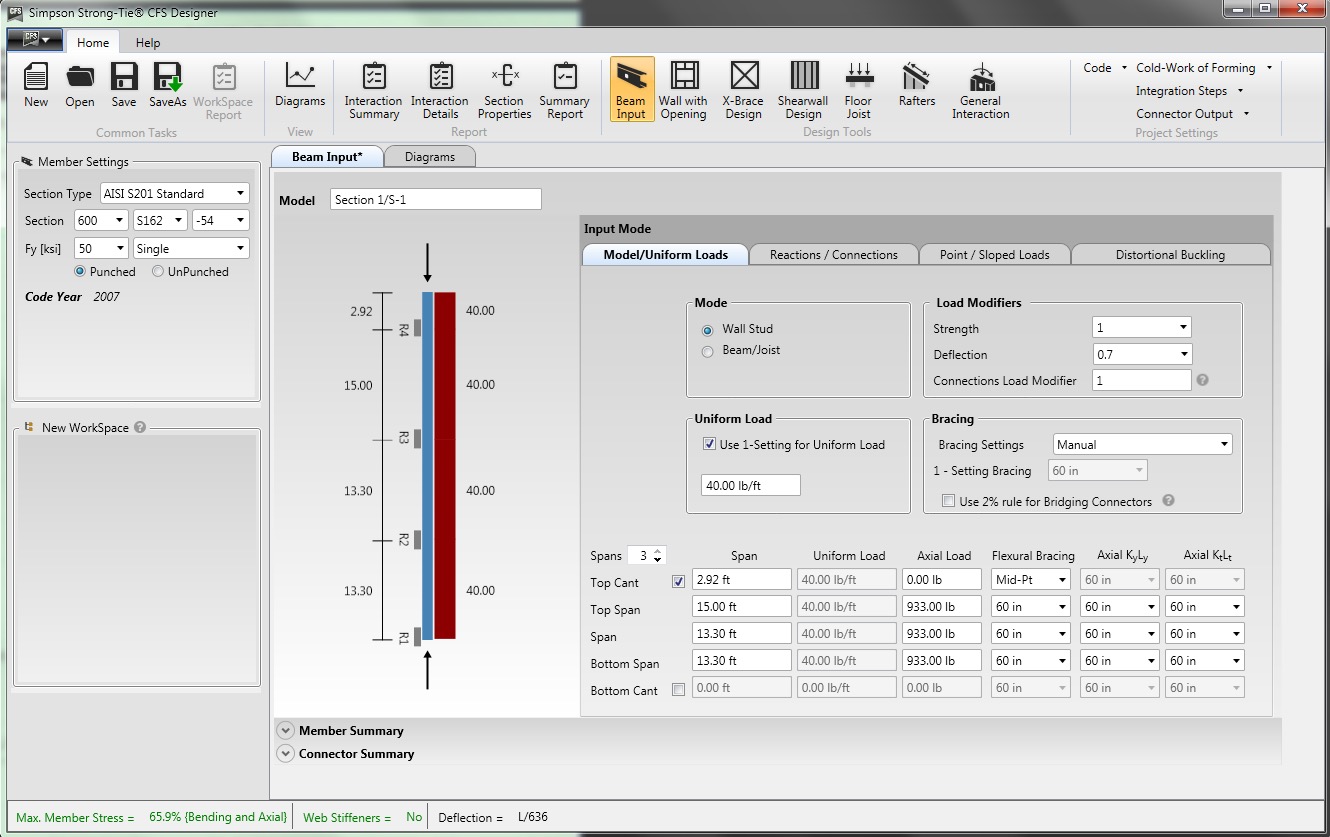
CFS Designer is a structural engineering design program that can automate many of the manual steps that are required in the design process. It has an easy-to-understand graphical user interface that allows you to input your project parameters within a variety of design modules from walls and beams, jambs and headers, X-brace walls, shearwalls, floor joists, and roof rafters. The program also enables the design of single stud or track members, built-up box-sections, back-to-back sections, and nested stud or track sections. Figure 5 shows an example of how you would input the same stud we looked at before into the program.
The program will generate the loading diagrams and complete calculation package for all of these different situations. And along with checking the member properties and deflection limits, CFS Designer will also check bridging and bracing requirements and provide connector solutions for the studs using tested and code-listed Simpson Strong-Tie products. Figure 6 shows an example of the summary output you would receive.
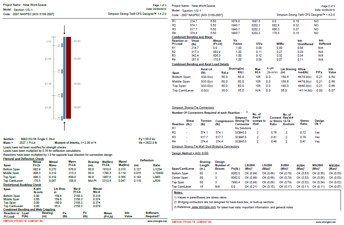
One unique part of the output is toward the center of the second page, under the heading “Simpson Strong-Tie Connectors.” This section summarizes the tension and compression loads at each reaction point and then shows a connector solution (such as the SCB45.5) along with the number of screws to the stud and the number of #12 sheet-metal screws to anchor back to the base building. Simpson Strong-Tie has developed and tested a full array of connectors specifically for CFS curtain-wall construction as well as for interior tenant improvement framing, which allows designers to select a connection clip straight out of a catalog without needing to calculate their own designs per the code. It’s just another way we’re helping you to get a little leaner!

The last part of the output shown in Figure 6 is titled “Simpson Strong-Tie Wall Stud Bridging Connectors.” It checks the bridging and bracing requirements per AISI S100 and selects a SUBH bridging connector, an innovative bridging solution developed by Simpson Strong-Tie that snaps into place and achieves design loads while only requiring one #10 screw to connect for 75% of applications.
You can download a free trial of CFS Designer™ and give it a test drive to see how much time it can save you on a design project. The trial version has almost full functionality, with the exception of not being able to print the output sheets. You can see purchasing information online, and you should always feel free to contact your local Simpson Strong-Tie engineering department with any questions you may have. I hope you are able to take advantage of this great tool to further improve your everyday design processes. We will be sure to keep you updated on our latest technology tools that help speed up the design process. If you’re using CFS Designer, we’d like to hear your thoughts about the program. Please share them in the comments below.

Specifying Self-Drilling Screws: “Standard” vs. “Engineered”
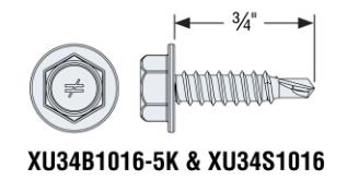
In my past life as a Design Engineer, when specifying a screw the size of the screw was the key feature that I considered. In my mind, a #10 screw performed better than #8, and a #12 was better than #10 and all #10 screws were the same. But that is not always true. Just as a shoe size or a dress size may not be exactly the same for all brands, a screw of the same size from different manufacturers may perform differently. The head type, head design, thread design (fine, coarse, thread angle, pitch), thread type (like box threads, buttress threads, unified, square) and drill point type (like #1, #3, #5 drill point) can influence the performance of a screw. When innovatively designed, a #10 engineered screw can meet or exceed the performance of a #12 or #14 screw in loads and drill time and could result in cost savings. You can use fewer screws, which would mean labor savings. For example, our newly designed XU34B1016 screw, which is a #10 screw with 16 threads per inch, a hex washer head and a #1 drill point, that performs better than a #14 standard screw in lighter gauge steels.
What Are Self-Drilling Tapping Screws?
Self-drilling tapping screws, or self-drilling screws, as the name implies, drill their own hole, eliminating the need for predrilling, and form or cut internal mating threads. They are relatively fast to instal compared to bolts or welds. Unlike pins, they do not require a thick support material to be used. They can be used in very thin steel, such as 26 gauge, up to steel that is ½” thick. Self-drilling screws may be a perfect choice for most applications involving cold-formed steel (CFS). They are most commonly used for CFS connections: either attaching CFS to CFS, wood to CFS or CFS to wood. They are a logical choice when the other side of the connection or material is not accessible.
Most self-drilling screws are made of steel wire that meets the specification of ASTM A510 minimum grade 1018 material as specified in ASTM C1513 standard. Self-drilling screws are heat treated to case harden then so that they meet the hardness, ductility, torsional strength and drill drive requirements as specified in ASTM C1513 standard. ASTM C1513 refers to SAE J78 for the dimensional and performance requirements of self-drilling screws.
Screw Selection
While selecting the screw, you need to figure out the head type that works for the application. For example, a flat-head screw would be a good choice for wood-to-steel applications, but for steel-to-steel applications, a hex head or a pan head may be a better choice. Similarly, the length of the screw should be sufficient to fasten the members of the connection together. According to Section D1.3 of AISI S200, the screw should be at least equal in length to the total thickness of the material including gaps with a minimum of three exposed threads. The length of the drill point is another important feature to consider. It should be long enough to drill through the entire thickness of the material before engaging the threads. This is because thread forming occurs with fewer revolutions than the drilling process. if the drill point length is not long enough, the screw threads can engage the connection material and the screw can bind and break.
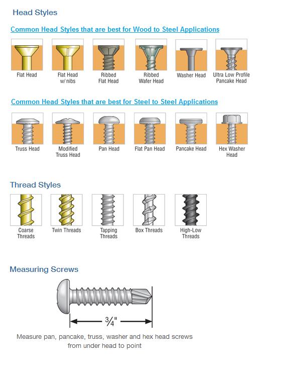
Some drill points also have “wings” to drill a hole in the material that is larger in diameter than the threaded shank. Screws with this kind of point are mainly used for wood-to-steel applications. The blog post by Jeff Ellis titled “Wings or No Wings” provides some useful insights for screws with wings when used in shearwall applications.
The Test Standards and Evaluation Criteria for Standard and Engineered Screws
Per Section D1 of AISI S200, screws used for steel-to-steel connections or sheathing-to-steel connections shall be in compliance with ASTM C1513 or an approved design or design standard.
For ASTM C1513–compliant screws (per AISI S100), Section J4 provides equations to calculate shear, pullout and pullover of screws used in steel-to-steel connections. It also provides safety and resistance factors for calculating allowable strength or design strength. These equations are based on the results of tests done worldwide and the many different types of screws used in the tests. As a result, these equations seem to have a great degree of conservatism.
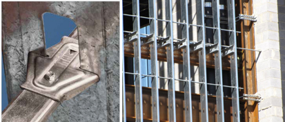
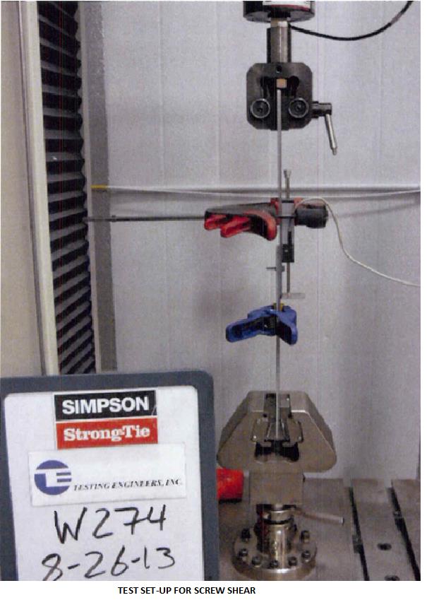
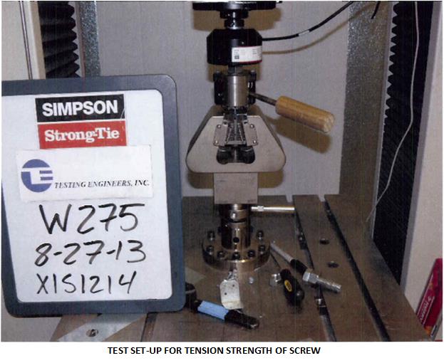
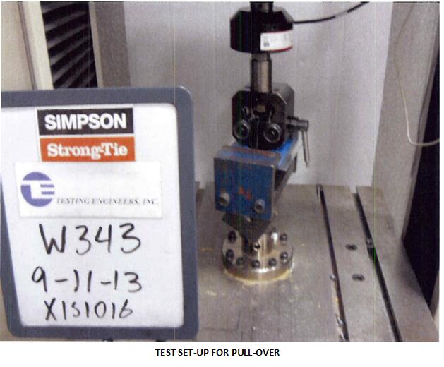
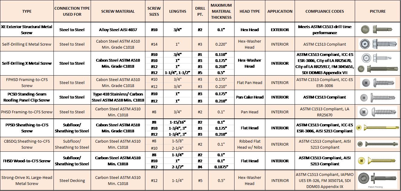
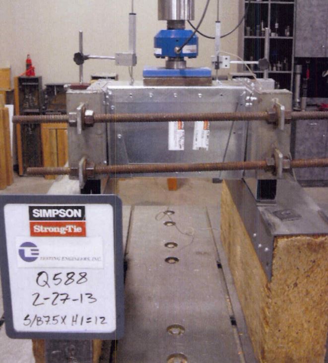
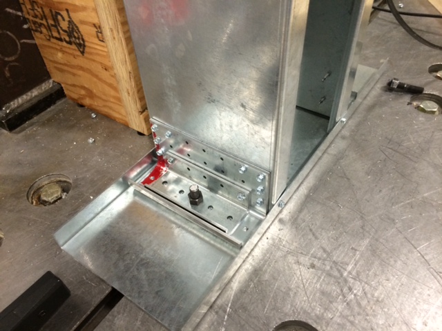
As discussed earlier, many factors, such as the head type and washer diameter, thread profile, drill point type and length, installation torque and the installation method affect or influence the performance of a screw. In order to qualify the screws as ASTM C1513–compliant or better performing, manufacturers need to have their screws evaluated per Acceptance criteria for Tapping Screw Fasteners AC118 developed by International Code Council – Evaluation Service. The criteria have different requirements depending on whether the intention is to qualify as standard screws or proprietary screws. For proprietary screws, connection shear, pullout and pullover tests are performed in accordance with the AISI S905 test method. The shear strength and tensile strength of the screw itself are evaluated per test standard AISI S904. The safety and resistance factors are calculated in accordance with Section F of AISI S100. The pictures below are some test set-ups per AISI S905 and AISI S904 test procedures.
Another important consideration is corrosion resistance. AC118 has a requirement for testing the fasteners for corrosion resistance in accordance with ASTM B117 for a minimum of 12 hours. The screws tested shall not show any white rust after 3 hours or any red rust after 12 hours of the test. At the same time, it is important to keep in mind that hardened screws are prone to hydrogen embrittlement and are not recommended for exterior or wet condition applications. Also, these screws are not recommended for use with dissimilar metals. If self-drilling screws are to be used in exterior environments, the screws need to be selectively heat treated to keep the core and surface hardness in a range that reduces the susceptibility to hydrogen embrittlement. Other fastener options for exterior environments are stainless-steel screws.
This table shows are some of our screw offerings for CFS applications. Our stainless-screw options can be found in Fastening Systems Catalog (C-F-2025) or at www.strongtie.com.
What are the screws that you most commonly specify? Share your screw preferences and your ideas on self-drilling screws in your comments below.
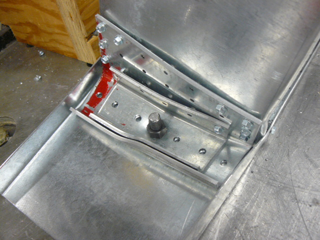
Don’t Buckle at the Knees: RCKW Testing
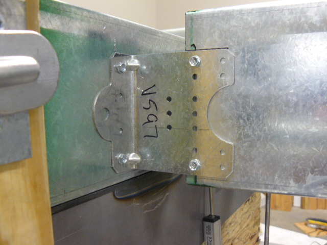
A previous blog post described how Simpson Strong-Tie tests and loadrates connectors used with cold-formed steel structural members per acceptance criteria ICC-ES AC261.
This week, I would like to describe how we test and determine engineering design values for RCKW, Rigid Connector Kneewall, in a CFS wall assembly and how the data can help designers perform engineering calculations accurately and efficiently.Continue Reading
Cold-Formed Steel Connectors
This blog has described how we load rate different products based on test standards, which are covered under various ICC-ES Acceptance Criteria, or ACs. The first was a post on wood connectors (AC13), then holdowns (AC155), threaded fasteners (AC233) and cast-in-place anchors for light-frame construction (AC398 and AC399). I realized today that I have never talked about how we test and load rate connectors for cold-formed steel.
But first, a confession – it has taken me many years to stop calling it “light-gauge steel.” When I started designing with cold-formed steel, I called it “light-gauge” because I had a binder of design information put together by the Light Gauge Steel Engineers Association. Advocates for CFS felt that “light-gauge” may make people think “weak” or “non-structural,” and that perception would limit the use of cold-formed steel in construction. So there was a deliberate effort to banish the word light-gauge and replace it with cold-formed steel, or CFS. I still slip every once in a while.
Connectors for light-gauge, ahem, I mean cold-formed steel members are covered under ICC-ES AC261 – Acceptance Criteria for Connectors Used with Cold-formed Steel Structural Members. The physical testing for cold-formed steel is similar to wood connectors. Build a setup representative of field conditions, apply load till failure and measure the load and deflection data. Both wood-to-wood and CFS connectors have a service limit state of 1/8” deflection.
Strength data for CFS connectors is analyzed much differently, however. Wood connectors generally use a safety factor of 3 on the lowest ultimate load (or average ultimate if six tests are run). We are often asked what the safety factor for CFS connectors is.
AISI S100 Chapter F details how to determine design strengths for tested CFS products. The design strength is the average test value, Rn, multiplied by an LRFD resistance factor, Φ, or divided by an ASD safety factor, Ω. Determining the resistance factor or corresponding safety factor is based on a statistical analysis dependent on several variables. This is similar in concept to how embedded concrete connectors tested to AC398 or AC399 are evaluated, which I discussed in this post.
I don’t want to get too deep into the Greek letters involved in the calculation. The factors that affect the allowable load calculation are type of member tested, variation in the test values, type of manufacturing, and number of samples tested. One factor that has a large impact on the calculation is the target reliability index, βo. In connector testing, this factor is 2.5 if the structural member (joist, stud, track, etc) fails and 3.5 if the connection fails. The net result is a higher safety factor for test values limited by the connection, and lower safety factors if the structural members governed the test load. Typical safety factors for CFS connectors are 1.8 to 2.0 where the failure mode is in the structural members and 2.2 to 2.9 for tests where the connection failed.
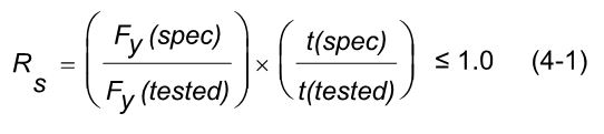
AC261 has a reduction factor, RS, which is used to adjust test values if your steel strength and/or steel thickness are over the specified minimum. CFS test setups often use different steel in the joist, header and the connector. Reductions are calculated based on the tested and specified strength and thickness for each member. The lowest reduction is used to adjust the test values.
One additional complexity in CFS testing is the multiple gauges of steel which must be evaluated. This requires more CFS test setups than a comparable wood connector would require. In the end, we have what we are really after. Design loads that specifiers can be confident in.

Midrise of Steel

The number of midrise structures constructed using light-frame cold-formed steel (CFS) certainly seems to be increasing each year. As with any material, there are benefits and challenges, especially in areas of moderate to high seismic risk. This post will discuss these as well as potential solutions.
Light-frame CFS midrise construction often uses ledger floor framing primarily to facilitate the load transfer detailing at the floor, tension anchorage (tie-downs or hold-downs) and compression chord studs or posts designed to resist the amplified seismic overturning loads. CFS framing is typically thin and singly symmetric.

Amplified Seismic Load
The AISI Lateral Design standard (AISI S213-07/S1-09) Section C5.1.2 requires that the nominal strength of uplift (tension) anchorage and the compression chord studs for shear walls resist the lesser of (1) the amplified seismic load or (2) the maximum load the system can deliver when the response modification coefficient, R, greater than 3. The amplified seismic load is defined as the load determined using the ASCE 7 seismic load combinations with the overstrength factor, Wo, which may be taken as 2.5 for CFS framed shear wall systems with flexible diaphragms.
Typically, the maximum the system can deliver to the uplift anchorage or chord studs is taken as the forces determined using the nominal shear strength of the shear wall assembly tabulated in the seismic shear wall table in S213 multiplied by 1.3. The S213 commentary accounts for the tabulated loads being based on Sequential Phased Displacement (SPD) rather than CUREE cyclic protocol and the degraded backbone curve. See the Structure magazine article that discusses the design of CFS framed lateral force-resisting systems.
Continuous Rod Tie-Down Systems
Light-framed CFS over three stories often use continuous rod tie-down systems rather than cold-formed steel hold-downs to resist shear wall overturning forces as they offer increased load capacity. Neglecting the dead load contribution, the amplified seismic load requirement for CFS shear walls using an R greater than 3 results in an 80% increase in the load used to size the continuous rod tie-down system compared to design level loads. For shear walls using an R greater than 3, it is important to note on the design drawings whether the uplift loads shown are ASD, LRFD, amplified ASD or amplified LRFD so the appropriate tie-down system may be designed.
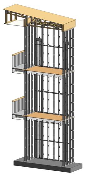
Continuous rod tie-down systems are designed not only for strength, but also checked to ensure they do not deflect too much to cause the top of shear wall drift to exceed the code limit or to exceed the 0.20” vertical story deflection limit required by some jurisdictions and ICC-ES AC316. Take-up devices are used in CFS framed structures to take-up construction and settlement gaps that may occur. AISI S200 Section C3.4.4 states that a gap of up to 1/8” might occur between the end of wall framing and the track. The vertical elongation of the continuous rod tie-down system includes rod elongation (PL/AE) and the take-up device deflection due to the seating increment and the deflection under load.
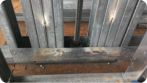
In addition, coordination is important in using continuous rod tie-down systems in CFS structures because the walls are often prefabricated offsite. An example is the consideration of the appropriate detail for the steel bearing plate installed at the floor sheathing in the story above to resist the uplift (tension) force from the story below.
One possible detail is to install the bearing plate in the bottom CFS track under all the CFS chord studs, but it’s important to ensure the bottom track flanges are deep enough to screw them to the stud flanges as the bearing plate can have a thickness of 1 ½” or more and typical tracks use 1 ¼” flanges. It is also important to ensure that the bearing plate width fits in the track. Another possible detail is to install the bearing plate under the CFS track under all the CFS chord studs. However, then it must be cut into the floor sheathing and may cause the bottom track to be raised at the bearing plate. For this detail, the floor shear transfer must be detailed through the ledger into the CFS framing.
Concrete Tension Anchorage
The concrete tension anchorage is designed according to ACI 318 Appendix D using the continuous steel rod material and size in accordance with S213 to have the nominal strength to resist the lesser of the amplified seismic force or the maximum load the system can deliver. ACI 318-11 Section D.3.3.4.3 offers four force limits for design of concrete tension anchorage design in Seismic Design Category C through F:
(1) The concrete nominal tension anchorage strength shall be greater than 1.2 times the ductile steel rod nominal tension anchorage strength
(2) The anchorage design strength shall be greater than the maximum tension force that can be delivered by a yielding attachment;
(3) The anchorage design strength shall be greater than the maximum tension force that can be delivered by a non-yielding attachment; and
(4) The anchorage design strength shall be greater than the amplified seismic force.
Typically either option (1) or (4) is used where (1) would lead to less concrete required than (4) if the bolt is efficiently sized while (4) would be required for such conditions as a vertical irregularity. See the concrete anchorage and podium anchorage SE Blog posts for more details.

CFS Wall Stud Bracing
CFS studs are typically thin and singly symmetric and thus require bracing. AISI S211 (Wall Stud Design Standard) permits two types of bracing design that cannot be combined; sheathing based or steel based. There are limits on the stud axial strength when using sheathing braced design. It’s important to identify on the drawings that the sheathing braces the studs and another load combination must be used for the stud design.
2012 IBC Section 2211.4 requires stud bracing to be designed using either AISI S100 (North American Specification) or S211 (Wall Stud Design Standard). S100-07 Section D3.3 required nominal brace strength is to be 1% of the stud’s nominal compressive axial strength, but S100-12 Section D3.3 changes this to the required brace strength is to be 1% of the stud’s required compressive axial strength (demand load). In addition, D3.3 requires a certain stiffness for each brace. AISI S211 required brace strength is to be 2% of each stud’s required compressive axial strength for axially loaded studs and, for combined bending and axial loads, be designed for the combined brace force per S100 Section D3.2.2 and 2% of the stud’s required compressive axial strength.
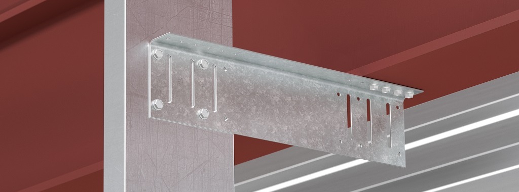
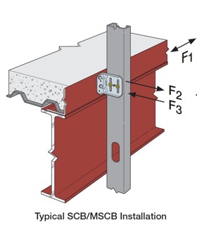
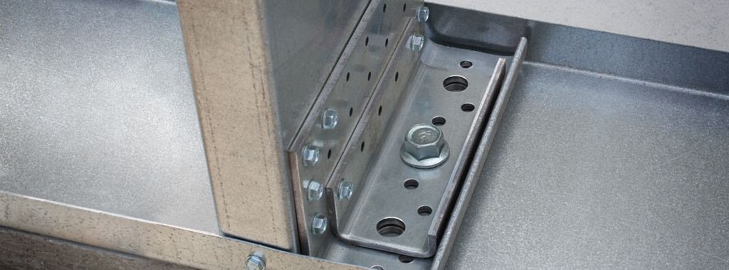
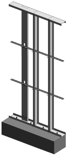
There are two primary types of steel stud bracing systems: bridging and strap bracing. U-channel bridging extends through the stud punchouts and is attached to the stud with a clip, of which there are various solutions such as this post on Wall Stud Bridging. Bridging bracing requires coordination with the building elements in the stud bay. It installs on one side of the wall, and does not bump out the wall sheathing. It also requires periodic anchorage to distribute the cumulative bracing loads to the structure for axially loaded studs often using strongback studs and does not require periodic anchorage for laterally loaded studs since the system is in equilibrium as the torsion in the stud is resisted by the U-channel bending.
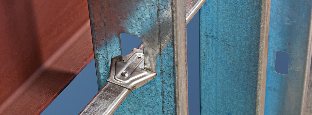
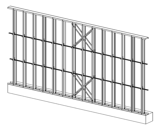
Flat strap bracing is installed on either side of the wall and at locations other than the stud punchout. It bumps out the sheathing and requires periodic anchorage to distribute the cumulative bracing loads to the structure for axially and laterally loaded studs.
![]()

![]()
Light-frame cold-formed steel construction has been used successfully for many projects, but there are challenges that must be addressed to ensure code compliance and desired performance. Some beneficial resources for designing CFS structures are the SEAOC 2012 IBC Structural/Seismic Design Manual Volumes 1 and 2 and the Cold-Formed Steel Engineers Institute’s (CFSEI) website where you can find technical notes and design guides.
What have been some of your observations or challenges in designing cold-formed steel midrise structures?

CFS Framed Shear Walls – A Code History

In a previous blog post, I talked about the challenges engineers may face when designing cold-formed steel and some resources available. When designing a building to the current building code, it can be helpful for engineers to understand the history of the different code requirements. This week I will discuss the code development history of CFS framed shear walls.
Prior to the 1997 Uniform Building Code (UBC), there were limited code provisions for design of cold formed steel-framed shear walls. The 1994 UBC had seismic R-factors for light-framed walls, but little else with respect to design or detailing. Code provisions were introduced in the 1997 UBC that included: