


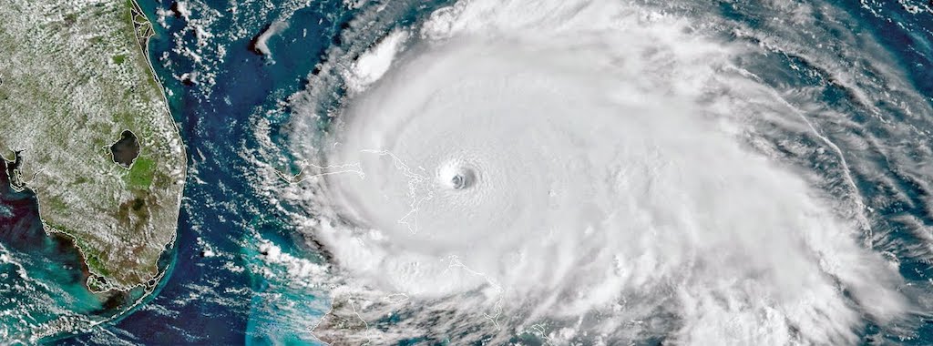
Last week marked the 30th anniversary of the Florida landfall of Hurricane Andrew, one of the most damaging, and influential, hurricanes ever to hit the United States. Hurricane Andrew hit South Florida with Category 5 winds early on the morning of August 24, 1992. Andrew caused damages of $25 billion in Florida, and another billion dollars’ worth when it struck Louisiana as a Category 3 hurricane two days later. This image, from NASA Earth Observatory, shows Andrew on August 23, 24, and 25.
Category: High Wind
High-wind forces pose unique dangers — and thus unique challenges — to building structures. Whether you’re a specifier, builder or homeowner, our state-of-the art design solutions and comprehensive resources can help you prepare and protect structures against damage due to high-wind events. From our extensively tested products to a wealth of tools and training, we have the knowledge and the products to keep your building safe and strong.
Damage Assessment and What It Teaches Us About How to Build Stronger
Over the past few years that I’ve worked as an engineer for Simpson Strong-Tie in Texas, work-related events have brought me to a few great beach destinations: Clearwater and Destin, Florida, to name a few. But tightly packed schedules always left me feeling like I didn’t get to enjoy the fullness of the locations I visited. So I made a short-term goal to fulfill a bucket-list item: Enjoy a beach vacation.
Not long after setting that goal, I actually had an opportunity to visit the Bahamas. Unfortunately, it wasn’t for the beach vacation I imagined, but rather to survey the catastrophic destruction wrought by Hurricane Dorian. With the one-year anniversary of that hurricane on September 1 and hurricane season already hitting us hard with Hurricane Laura, I thought it would be good to revisit my observations from that trip.
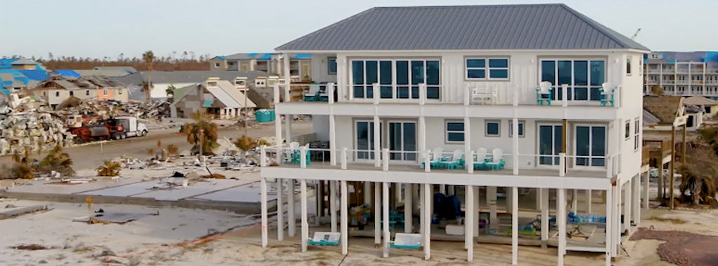
Choosing Resiliency: Lessons from Hurricane Michael
In this post, Doug Allen, P.E., a structural engineer with Simpson Strong-Tie, looks at the choice homeowners in disaster-prone areas face between simply building to code and building to standards of resilience or IBHS FORTIFIED Home™ standards instead.
Resilience, or resiliency: The capacity to recover quickly from difficulties; toughness. The ability of a substance or object to spring back into shape; elasticity.
In the wake of the most recent and very devastating hurricane seasons, the theme of structural resiliency has resurfaced with renewed urgency for increasing numbers of homeowners, builders, Designers and civic planners. Hurricanes pose a triple threat of high winds, substantial rain and storm surge. Extreme weather has cost the nation nearly $100 billion in damage during 2018. Accordingly, awareness has risen within affected and surrounding coastal regions regarding their communities’ existing structural resilience ratings (low or high) and the need to improve in view of the losses as well as the time and cost to rebuild what was destroyed.
Continue Reading

What You Need to Know About Differences in Wind-Speed Reporting for Hurricanes
There is a great deal of good information out there to help us better understand hurricanes and their impact on people, structures and other property. To improve awareness of wind speeds and their measurement, this article will discuss a commonly misunderstood aspect of hurricane wind-speed reporting.
Continue Reading
Keep Your Roof On
He huffed, and he puffed, and he blew the roof sheathing off! That’s not the way kids’ tale goes, but the dangers high winds pose to roof sheathing are very real. Once the roof sheathing is gone, the structure is open and its contents are exposed to the elements and much more vulnerable to wind or water damage. It is a storyline that we meet all too often in the news.
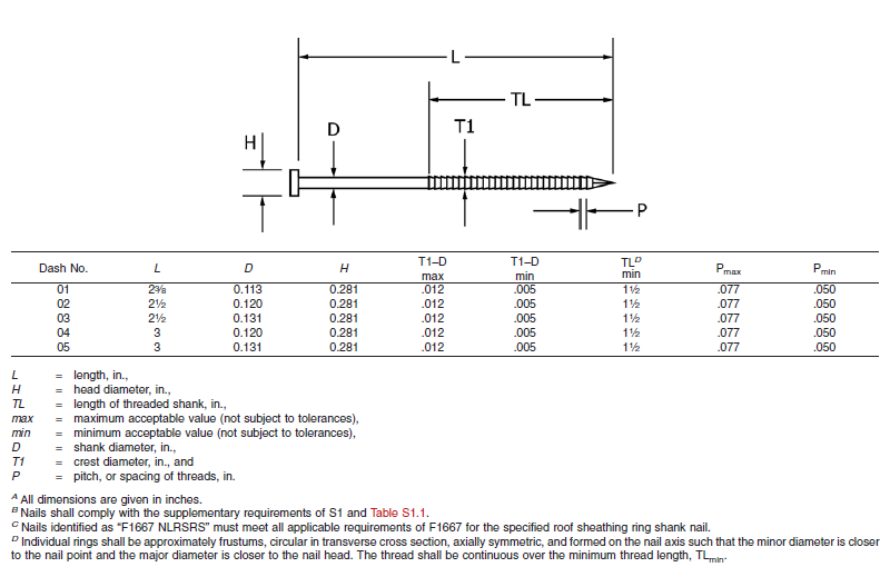
About two years ago, the ASTM subcommittee on Driven and Other Fasteners (F16.05), addressed fastening for roof sheathing in high-wind areas by adding a special nail to ASTM F1667-17 – Standard Specification for Driven Fasteners: Nails, Spikes and Staples. The Roof Sheathing Ring-Shank Nail was added to the standard as Table 46. Figure 1 illustrates the nail and lists its geometrical specifications. This is a family of five ring-shank nails that can be made from carbon steel or stainless steel (300 series). Specific features of these nails are the ring pitch (number of rings per inch), the ring diameter over the shank, the length of deformed shank and the head diameter. Also, note B specifies that the nails shall comply with the supplementary requirement of Table S1.1, which tabulates bending yield strength. In this diameter class, the minimum bending yield strength allowed is 100 ksi.
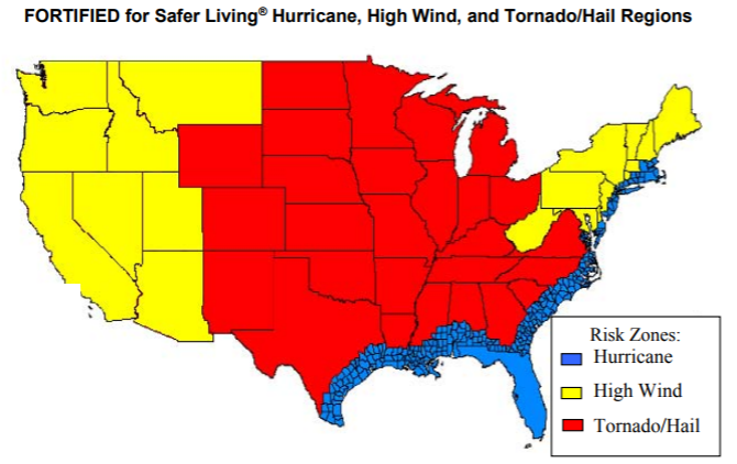
The IBHS (Insurance Institute for Business and Home Safety) discusses roof deck fastening in its Builders Guide that describes the “FORTIFIED for Safer Living” structures. The IBHS FORTIFIED program offers solutions that reduce building vulnerability to severe thunderstorms, hurricanes and tornadoes. Keeping the roof sheathing on the structure is critical to maintaining a safe enclosure and minimizing damage, and roof sheathing ring-shank nails can be part of the solution. As Figure 2 from IBHS (2008) shows, every wood-frame structure has wind vulnerability.
More importantly for the wood-frame engineering community, the Roof Sheathing Ring-Shank Nails are being included in the next revision of the AWC National Design Specification for Wood Construction (NDS-2018), which is a reference document to both the International Building Code and the International Residential Code. You will be able to use the same NDS-2018, chapter 12 withdrawal equation to calculate the withdrawal resistance for Roof Sheathing Ring-Shank Nails and Post Frame Ring-Shank nails. The calculated withdrawal will be based on the length of deformed shank embedded in the framing member. Also, Designers need to consider the risk of nail head pull-through when fastening roof sheathing with ring-shank nails. If the pull-through for roof sheathing ring-shank nails is not published, you will be able to use the new pull-through equation in the NDS-2018 to estimate that resistance.
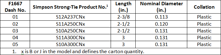
Simpson Strong-Tie has some stainless-steel products that meet the requirements for Roof Sheathing Ring-Shank Nails. These will be especially important to those in coastal high-wind areas. Table 1 shows some of the Simpson Strong-Tie nails that can be used as roof sheathing ring-shank nails. These nails meet the geometry and bending yield strength requirements given in ASTM F1667. See the Fastening Systems catalog C-F-2017 for nails in Type 316 stainless steel that also comply with the standard.
Improve your disaster resilience and withstand extreme winds by fastening the sheathing with roof sheathing ring-shank nails. You can find Roof Sheathing Ring-Shank nails in ASTM F1667, Table 46, and you will see them in the AWC NDS-2018, which will be available at the end of the year. Let us know your preferred fastening practices for roof sheathing.
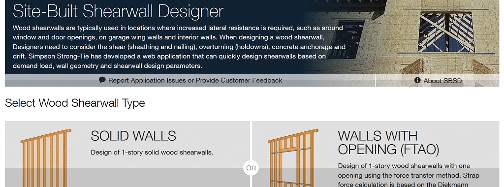
Introduction to the Site-Built Shearwall Designer Web Application
Wood shearwalls are typically used as a lateral-force-resisting system to counter the effects of lateral loads. Wood shearwalls need to be designed for shear forces (using sheathing and nailing), overturning (using holdowns), sliding (using anchorage to concrete) and drift, to list some of the main dangers. The Simpson Site-Built Shearwall Designer (SBSD) web app is a quick and easy tool to design a wood shearwall based on demand load, wall geometry and design parameters.Continue Reading
Designing Gable End Overhangs
It seems that each major hurricane tends to teach those of us in the construction industry some lesson. With Hurricane Andrew, the lessons were the importance of protection from windborne debris, and the importance of proper construction of gable end overhangs.
There are two main areas where gable ends can fail.
Concrete Anchorage for ASD Designs
One of the first things I learned in school about using load combinations was that you had to pick either Load and Resistance Factor Design (LRFD)/Strength Design (SD) or Allowable Stress Design (ASD) for a building and stick with it, no mixing allowed! This worked for the most part since many material design standards were available in a dual format. So even though I may prefer to use LRFD for steel and ASD for wood, when a steel beam was needed at the bottom of a wood-framed building that was designed using ASD load combinations, the steel beam could easily be designed using the ASD loads that were already calculated for the wood framing above since AISC 360 is a dual- format material standard. And when the wood-framed building had to anchor to concrete, ASD anchor values were available in the IBC for cast-in-place anchors and from manufacturers for post-installed anchors in easy-to-use tables, even though ACI 318 was not a dual-format material standard. (Those were good times!)
Then along came ACI 318-02 and its introduction of Appendix D – Anchoring to Concrete, which requires the use of Strength Design. The 2003 IBC referenced Appendix D for Strength Design anchorage, but it also provided a table of ASD values for some cast-in-place headed anchors that did not resist earthquake loads or effects. This option to use ASD anchors for limited cases remained in the 2006, 2009 and 2012 codes. In the 2015 IBC, all references to the ASD anchor values have been removed, closing the book on the old way of designing anchors.
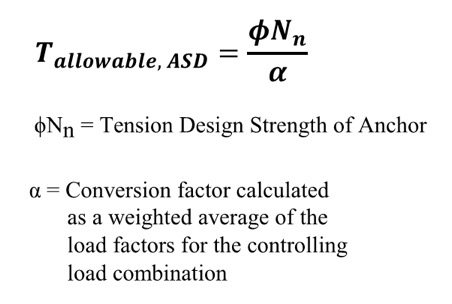 So what do you do now? Well, there is some guidance provided by ICC-ES for manufacturers to convert calculated SD capacities to ASD allowable load values. Since there is no conversion procedure stated in the IBC or referenced standards, designers may want to use this generally accepted method for converting anchor capacities designed using ACI 318. ICC-ES acceptance criteria for post-installed mechanical and adhesive anchors (AC193 and AC308) and cast-in-place steel connectors and proprietary bolts (AC398 and AC399) outline a procedure to convert LRFD capacities to ASD using a weighted average for the governing LRFD/SD load combination. So if the governing load combination for this anchor was 1.2D + 1.6L and the dead load was 1,000 pounds and the live load was 4,000, then the conversion factor would be (1.2)(0.2) + (1.6)(0.8) = 1.52 (keep in mind that the LRFD/SD capacity is divided by the conversion factor in the ICC-ES equation shown here for tension).
Right away, there are a few things that you may be thinking:
- What about load factors that may exist in ASD load combinations?
- It may just be easier to just recalculate my design loads using LRFD/SD combinations!
- The resulting allowable loads will vary based on the load type, or combination thereof.
- If the ACI 318 design strength is limited by the steel anchor, then the conversion will result in an allowable load that is different from the allowable load listed for the steel element in AISC 360.
Let’s take a look at these objections one by one.
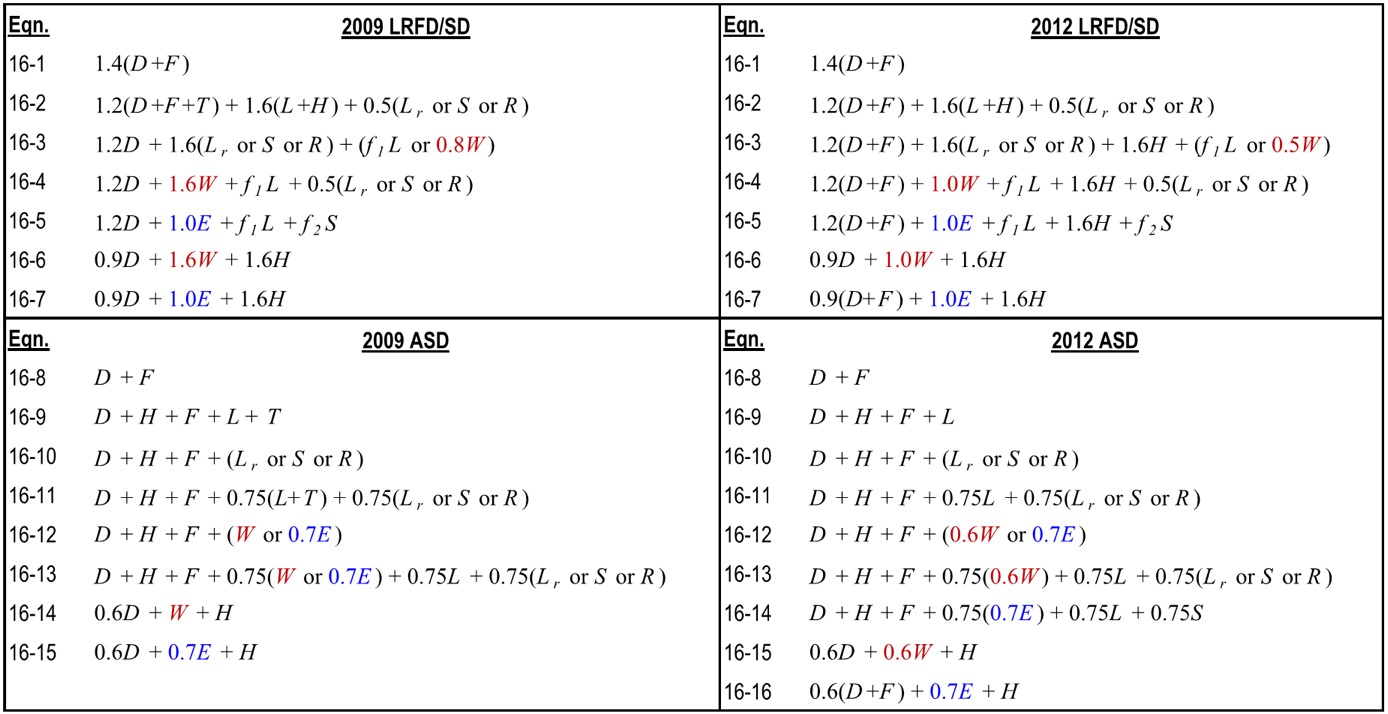
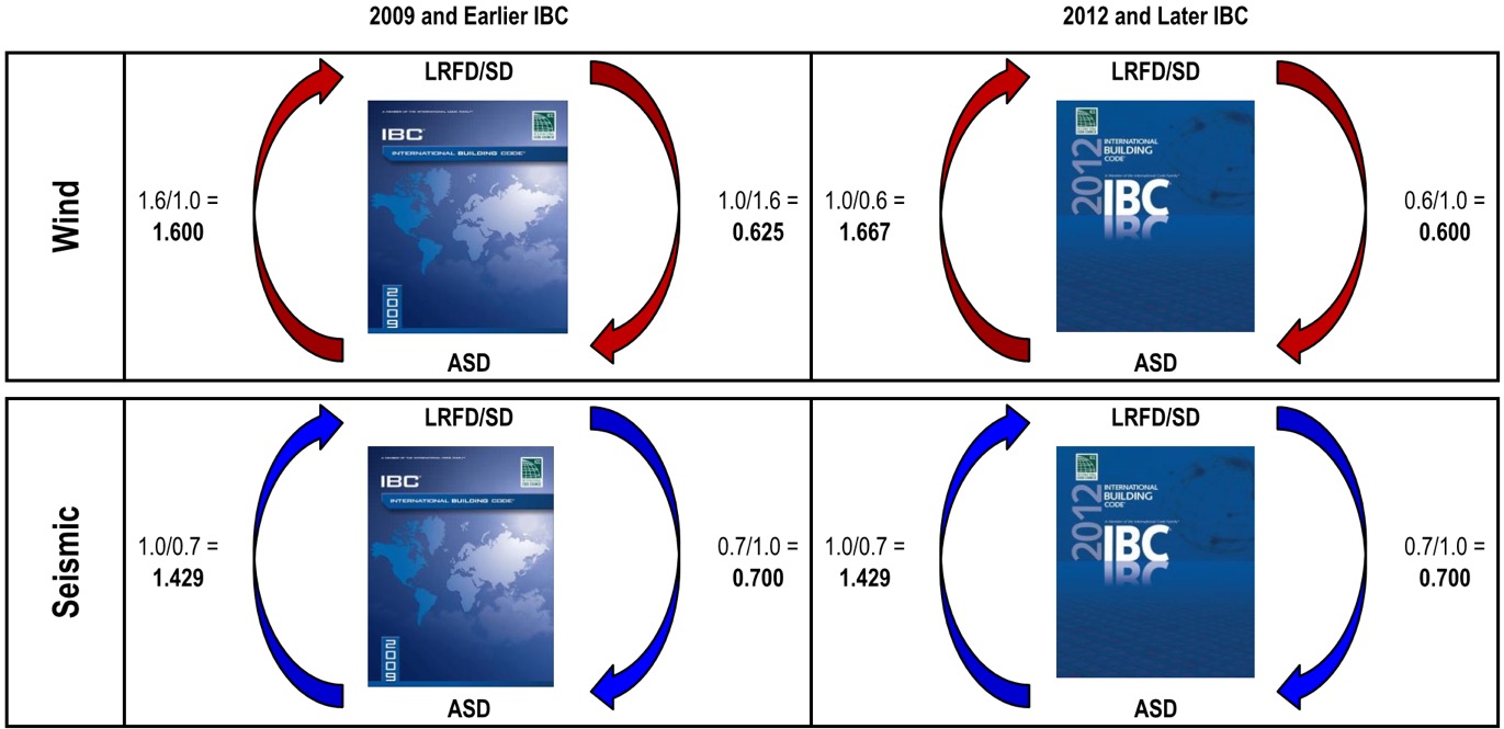
Item 1: Since unfactored earthquake loads are determined at the ultimate level in the IBC, they have an LRFD/SD load factor of 1.0 and an ASD load factor less than 1.0, which is also true for wind loads in the 2012 and 2015 IBC (see graphic below). Using the LRFD/SD load factor of 1.0 obviously does not convert the capacity from LRFD to ASD so you must also account for ASD load factors when calculating the conversion factor. To do so, instead of just using the LRFD load factor, use the ratio of LRFD Factor over ASD Factor. So if the governing load combination for an anchor was 0.9D + 1.0E and the dead load was 1,000 pounds and the seismic load was 4,000, then the conversion factor would be (0.9)(0.2) + (1.0/0.7)(0.8) = 1.32.
Item 2: Even though the weighted average conversion requires you to go back and dissect the demand load into its various load types, often this can be simplified. ICC-ES acceptance criteria permit you to conservatively use the largest load factor. The most common application I run into is working with ASD-level tension loads for wood shearwall overturning that must be evaluated using SD-level capacities for the concrete anchorage. Since these loads almost always consist of wind or seismic loads, using the largest factor is not overly conservative. Depending on the direction in which you are converting the demand loads or resistance capacities, the adjustment factors are as shown in the figure below. Affected Simpson Strong-Tie products now have different allowable load tables for each load type. (For examples, see pp. 33-36 of our Wood Construction Connectors catalog for wind/seismic tables and pp. 28-30 of our Anchoring and Fastening Systems catalog for static/wind/seismic tables.)
Item 3: I am unsure whether there is any sound rationale for having allowable loads for an anchor resisting 10% dead load and 90% live load differ from those of an anchor that resists 20% dead load and 80% live load. Perhaps a reader could share some insight, but I just accept it as an expedience for constructing an ASD conversion method for a material design standard that was developed for SD methodology only.
Item 4: We have differing opinions within our engineering department on how to handle the steel strength component of the various SD failure modes listed in ACI 318. Some believe all SD failure modes in ACI 318 should be converted using the load factor conversion method. I side with others who believe that the ASD capacity of a steel element should be determined using AISC 360. So when converting SD anchor tension values for a headed anchor, I would apply the conversion factor to the concrete breakout and pullout failure modes from ACI 318, but use the ASD steel strength from AISC 360.
Finally, I wanted to point out that the seismic provisions in ACI 318, such as ductility and stretch length, must be considered when designing anchors and are not always apparent when simply converting to ASD. For this reason, I usually suggest converting ASD demand loads to SD levels so you can use our Anchor Designer™ software to check all of the ACI 318 provisions. But for some quick references, we now publish tabulated ASD values for our code-listed mechanical and adhesive anchors in our C-A-2016 catalog — just be sure to read all of the footnotes!
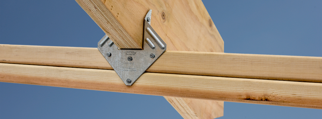
How to Select a Connector – Hurricane Tie
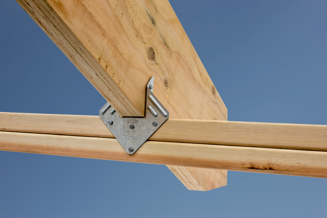
When it comes to wood-frame construction, hurricane ties are among the most commonly specified connectors. They play a critical role in a structure’s continuous load path and may be used in a variety of applications, like attaching roof framing members to the supporting wall top plate(s), or tying wall top or bottom plates to the studs. They are most commonly used to resist uplift forces, but depending on regional design and construction practices, hurricane ties may also resist lateral loads that act in- or out-of-plane in relation to the wall.
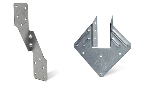
Simpson Strong-Tie manufactures approximately 20 different models of hurricane ties, not counting twist straps, other clips, or the new fully-threaded SDWC screws often used in the same applications. This assortment of models raises the question, “How do you select the right one?”
In this post, we’ll outline some of the key elements to consider when selecting a hurricane tie for your project.
Demand Load
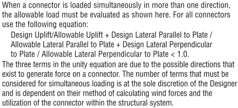
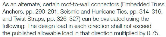
Let’s start with the obvious one. If your building’s roof trusses have an uplift of 600 lb. at each end, don’t select a hurricane tie with a published capacity of less than 600 lb. It’s also important to consider combined loading if you plan to use the tie to resist both uplift and lateral loads. When the connector is resisting lateral loads, its capacity to resist uplift is reduced. I won’t go into too much detail on this topic since it was covered in a recent blog post, but in lieu of the traditional unity equation shown in Figure 1, certain Simpson Strong-Tie connectors (hurricane ties included) are permitted to use the alternative approach outlined in Figure 2.
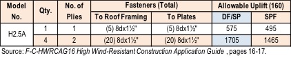
What if the tabulated loads in the catalog for a single connector just aren’t enough? Use multiple connectors! An important note on using multiple connectors, though: Using four hurricane ties doesn’t always mean you’ll get 4x the load. Check out the recently updated F-C-HWRCAG16 High Wind-Resistant Construction Application Guide for allowable loads using multiple connectors and for guidance on the proper placement of connectors so as to avoid potential overlap or fastener interference.
Dimensional Requirements
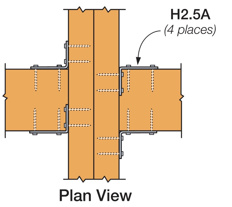
While the majority of the hurricane ties that Simpson Strong-Tie offers are one-sided (such as the H2.5A), some are designed so the truss or rafter fits inside a “U” shape design to allow for fastening from both sides (such as the H1). If using the latter, make sure the width of the truss or rafter is suitable for the width of the opening in the hurricane tie. For example, use our new H1.81Z (not the H1Z) for 1¾” wide engineered roof framing members.
Additionally, the height of the hurricane tie and the wood members being attached should be compatible. For example, an H2.5A would not be compatible with a roof truss configured with only a nominal 2×4 bottom chord over the plate since the two upper nail holes in the H2.5A will miss the 2×4 bottom chord (see Figure 7). This is actually such a common mis-installation that we specifically tested this scenario and have developed an engineering letter on it (note the greatly reduced capacity). In this case the ideal choice would be the H2.5T, which has been specifically designed for a 2×4 truss bottom chord.

Fasteners with Hurricane Ties
It’s also essential to pay close attention to the diameter and length of the fasteners specified in the Simpson Strong-Tie literature. While many hurricane ties have been evaluated with 8d x 1½” nails for compatibility with nominal 2x roof framing, some require the use of a longer, 8d common (2½” long) nail and others require a larger-diameter 10d nail.
When specifying products for a continuous load path, it’s a good idea to select connectors that all use the same size nail to avoid improper installations on the job. It’s much easier if the installer doesn’t need to worry about which size nail he currently has loaded in his pneumatic nailer.
Wall Framing
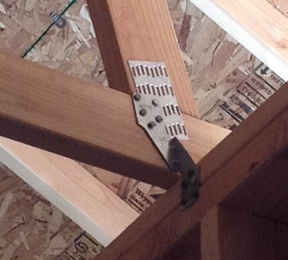
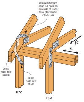
Do your roof and wall framing members line up? If so, creating a continuous load path can be made simpler by using a single hurricane tie to fasten the roof framing to studs. The H2A, H7Z, and H10S are some of the connectors designed to do just that. If your framing doesn’t align, though, you can use two connectors to complete the load path. For simplification and to reduce potential mix-ups in the field, consider selecting the same hurricane tie for your roof framing-to-top-plate and top plate-to-stud connections, like the H2.5A.
Besides the added benefit of fewer connectors to install, using a single hurricane tie from your roof framing to your wall studs can eliminate top-plate roll, a topic discussed at length in one of our technical bulletins.
Other Factors When Selecting Hurricane Ties
Some additional factors that may influence your selection of a hurricane tie are:
- Environmental factors and corrosion should be considered when selecting any product. Nearly every hurricane tie is available in ZMAX®, our heavier zinc galvanized coating, and several are available in Type 316 stainless steel. A full list of products available in ZMAX or stainless steel may be found on our website. On a related note, be sure to use a fastener with a finish similar to that of the hurricane tie in order to avoid galvanic corrosion caused by contact between dissimilar metals.
- When retrofitting an existing structure, local jurisdiction requirements will also influence your decision on which hurricane tie to use. As an example, the state of Florida has very specific requirements for roof retrofitting, which we outline in a technical bulletin, and they specifically mention the roof-to-wall connection. Be sure to check with your local city, county or state for specific requirements before you decide to retrofit.
- Availability of wind insurance discounts in your area could also affect your decision on which type of hurricane tie to use on your home. Your insurance company may provide a greater discount on your annual premium for ties that wrap over the top of your roof framing and are installed with a certain minimum quantity of nails. Check with your insurance provider for additional information and requirements.
Although this is a lot to take in, hopefully it makes choosing the right hurricane tie easier for you on your next project. Are there any other items you consider in your design that weren’t mentioned above? Let us know in the comments below.
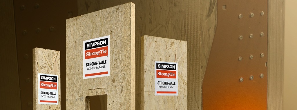
Simpson Strong-Tie® Strong-Wall® Wood Shearwall – The Latest in Our Prefabricated Shearwall Panel Line Part 2
In last week’s blog post, we introduced the Simpson Strong-Tie® Strong-Wall® Wood Shearwall. Let’s now take a step back and understand how we evaluate a prefabricated shear panel to begin with.
First, we start with the International Building Code (IBC) or applicable state or regional building code. We would be directed to ASCE7 to determine wind and seismic design requirements as applicable. In particular, this would entail determination of the seismic design coefficients, including the response modification factor, R, overstrength factor, Ωo, and deflection amplification factor, Cd, for the applicable seismic-force-resisting system. Then back to the IBC for the applicable building material: Chapter 23 covers Wood. Here, we would be referred to AWC’s Special Design Provisions for Wind and Seismic (SDPWS) if we’re designing a lateral-force-resisting system to resist wind and seismic forces using traditional site-built methods.Continue Reading