 This week’s post comes from Dan Harmon, an R&D engineer for Simpson Strong-Tie’s Infrastructure-Commercial-Industrial (ICI) group. Dan specializes in post-installed concrete anchor design and spent a decade managing Simpson’s anchor testing lab, where he developed extensive knowledge of anchor behavior and performance. He has a Bachelor of Science in mechanical engineering from the University of Illinois Urbana-Champaign.
Designers and engineers can spend hundreds of hours on detailed drawings of structures, but there are often conditions and coordination that can change well-planned details and drawings. As we all know, paper and reality don’t always agree. Anchorage locations can move as a result of unforeseen circumstances such as encountering reinforcing bars in an existing concrete slab or interference between different utility trades.
With post-installed anchors, one particular jobsite change may require abandoning a hole that has been drilled, leaving the final anchor location adjacent to the abandoned hole. When a hole for an anchor is drilled but never used, it essentially creates a large void in the concrete. Depending on where this void is located in relation to an installed anchor, there is potential for the capacity of that anchor to be reduced. To give guidance on this situation to specifiers, users and contractors, Simpson Strong-Tie conducted a large series of tests in their ISO 17025–accredited Anchor Systems Test Lab in Addison, Illinois.
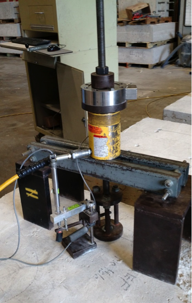
To evaluate the effect of abandoned holes located adjacent to post-installed anchors, we performed tension tests meeting the requirements of ASTM E488-15 (see Figure 1). A variety of anchor types with common diameters were tested:
- Drop-in anchors (1/2″ and 3/4″ diameter)
- Wedge-type anchors (1/2″ and 3/4″ diameter)
- Concrete screws (1/2″ diameter)
- Adhesive anchors with threaded rod (1/2″ diameter)
Each anchor type and diameter was tested under five different conditions:
- No abandoned hole near the installed anchor. This is considered the reference condition to which other tests are to be compared.
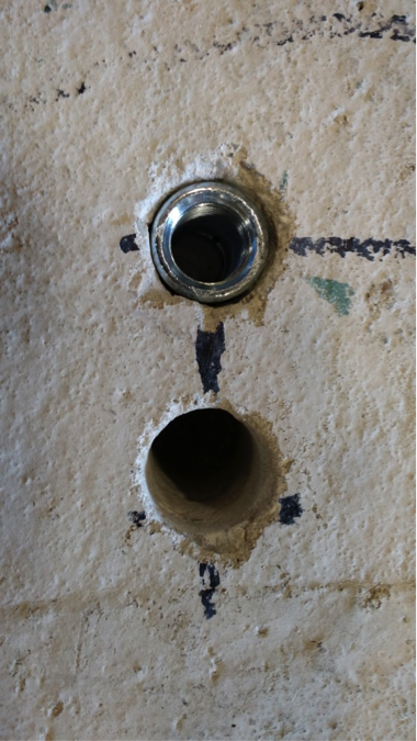
- One abandoned hole at a distance of two times the hole diameter (2d) away from the installed anchor. See Figure 2.
- One abandoned hole at a distance of four times the hole diameter (4d) away from the installed anchor.
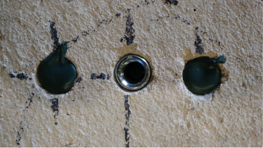
- Two abandoned holes, each at a distance of two times the hole diameter (2d) away from the installed anchor. In test conditions with two holes, the holes were located on either side of the installed anchor, approximately 180º from each other. See Figure 3.
- Two abandoned holes, each at a distance of two times the hole diameter (2d) away from the installed anchor, with the holes refilled with a concrete anchoring adhesive that was allowed to cure fully prior to testing. See Figure 4.

This test program is summarized in Table 1. In all cases, the abandoned hole was of the same diameter and depth as the hole prescribed for the installed anchor.
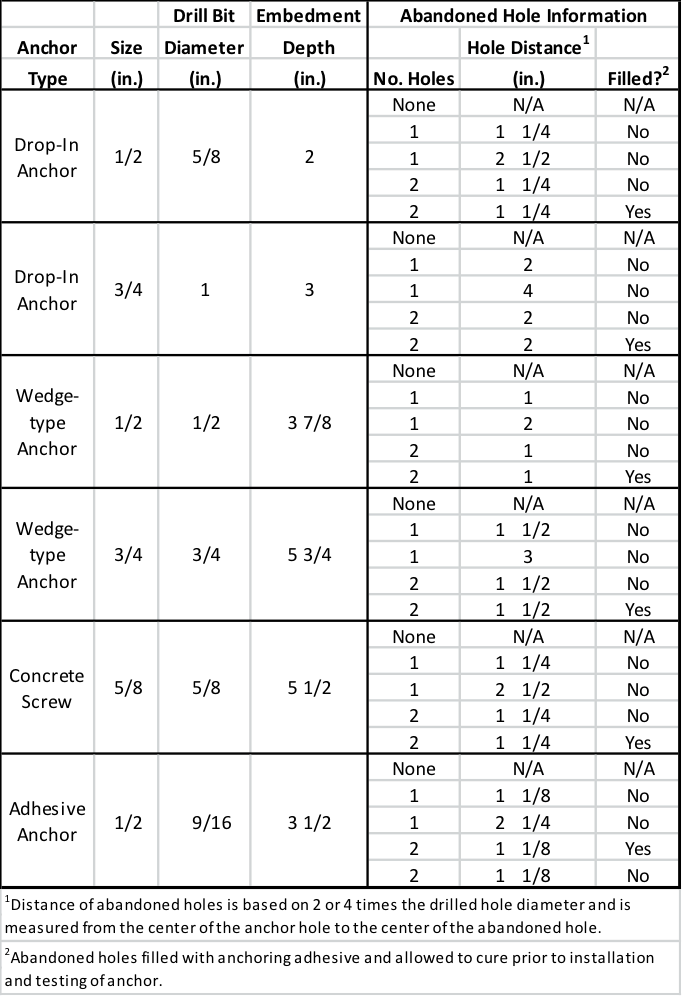
Five tests for each anchor under each condition were tested, and the mean and coefficient of variance of each data set were calculated. These calculated values were used to compare the different conditions.
Across the different anchor types and diameters, the test results showed a number of general rules that held true.
Summary Results
Abandoned holes that are 2” or more away from the anchor have little to no effect on the tension performance of the anchor. Compared to the reference condition with no abandoned hole near the anchor, conditions where the abandoned hole was sufficiently far away were found to be essentially equivalent. This equivalence held true even for anchor types that create expansion forces (drop-in and wedge-type anchors) during their installation.
Two abandoned holes have the same effect on performances as one, regardless of distance from the anchor. This testing showed that adding a second abandoned hole near an installed anchor did not adversely affect tension performance in a significant way. Even within distances of 2 inches, performance did not drop substantially – if at all – in conditions involving two abandoned holes as compared to one.
Filling abandoned holes with an anchoring adhesive prior to installation of the anchor improves performance. In all cases tested, filling abandoned holes with adhesives resulted in increased performance compared to leaving the holes empty. In a majority of cases, performance with filled holes was equivalent to performance in the reference condition regardless of the distance from the anchor.
When the abandoned hole is more than two times the drilled hole diameter but less than 2″from the anchor – and left unfilled – the testing showed a loss in performance. Not surprisingly, the degree of that loss was dependent on the type of anchor. Table 2 shows the capacity reduction compared to the reference condition in testing with expansion anchors. Table 3 shows the same results for concrete screws and adhesive anchors. Conservative suggested performance reductions in these conditions would be 20% for expansion anchors and 10% for concrete screws and adhesive anchors.


In an ideal world, the engineer’s designs could be followed at all times at the jobsite. But we don’t live in an ideal world. Good engineering judgment is needed in situations where variation is required, and having data to support those decisions is always helpful. In the case of abandoned holes near post-installed anchors, it’s Simpson Strong-Tie’s hope that this testing provides additional guidance for the designer, inspector, and jobsite worker.


